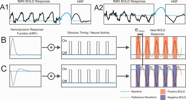
Figure 7.

An example of the effect of inverted HRFs on fMRI analysis. (A) Empirical fMRI time‐courses from polar angle mapping in voxels with (A1) positive and (A2) inverted HRFs. (B,C) Simulation illustrating error in temporal phase‐mapping analysis caused by an inverted HRF. Ideal BOLD responses were predicted by convolving HRFs (B–positive, C–inverted) with identical stimulus timing waveforms. Stimulus timing was for a quarter‐field checkerboard wedge rotating about the center of gaze five times. Despite identical timing of neural activity, the apparent phase delay is shifted by e delay for the voxel with an inverted HRF compared to that with a positive HRF.
