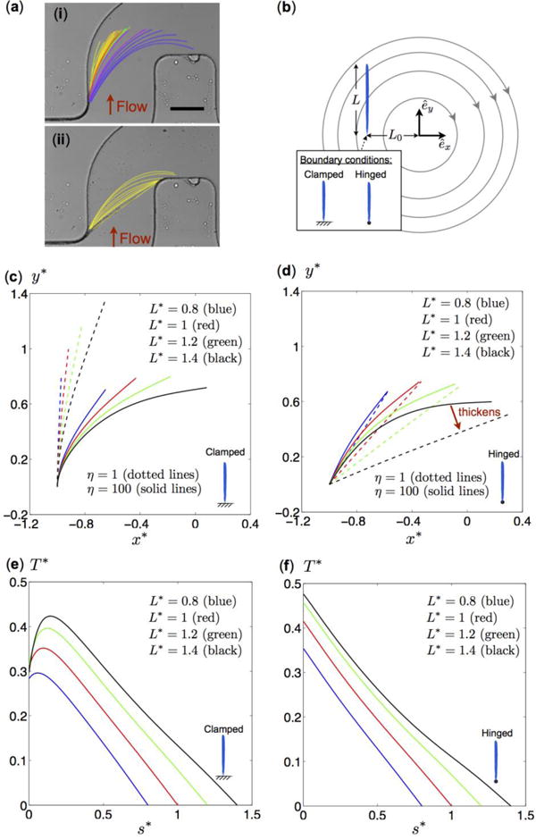
Figure 6.

(a) Image of a biofilm streamer during initial formation in a microfluidic channel where a bacterial cell concentration corresponding to OD600=0.5 was flowed through the channel by a syringe pump, which was set to a flow rate of 1.5 ± 0.05 μL/min. The red arrows indicate the flow direction: (i) The streamer grows in length and reorients in the clockwise direction towards the right corner of the channel. (ii) The streamer straightens as it becomes thicker. The scale bar represents 100 μm. (b) Schematic diagram of a model flow problem for a streamer of length L at a distance L0 from the origin in a flow with circular streamlines due to clockwise rigid body rotation. Two tethering conditions (vertically clamped and hinged filaments) are considered. (c, d) Steady-state shapes of vertically clamped filaments (c) and hinged filaments (d) of different lengths and flexibility (as indicated in the figure). The solid and dotted lines represent results for relatively rigid (η = 1) and flexible (η = 100) filaments, respectively. Colored lines correspond to filaments of dimensionless lengths L* = L/L0 0.8 (blue), L* = 1.0 (red), L* = 1.2 (green), and L* = 1.4 (black). The shapes are shown in terms of dimensionless coordinates x* = x/L0 and y* = y/L0. (e, f) Vertically clamped filaments and hinged filaments of dimensionless steady-state tension profiles (EQUATION), as a function of the dimensionless arc length s* = s/L along the flexible (η = 100) filaments. Colored lines correspond to different dimensionless lengths: L* = L/L0 = 0.8 (blue), L* = 1.0 (red), L* = 1.2 (green), and L* = 1.4 (black).
