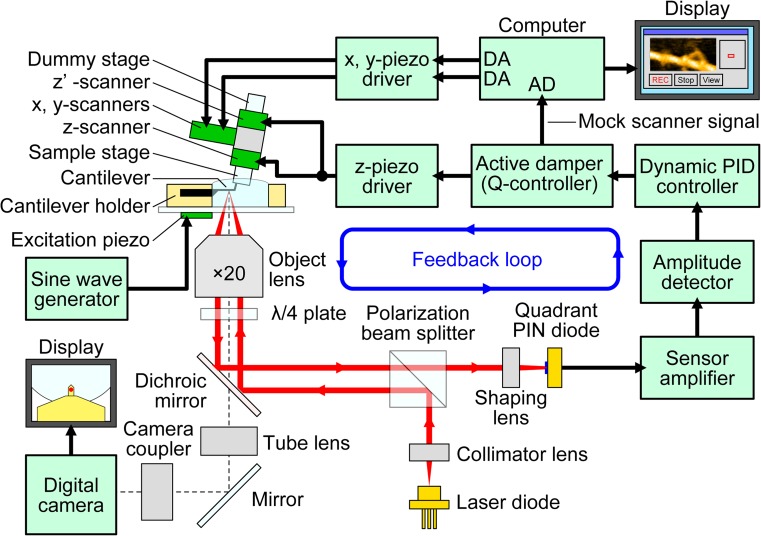
Fig. 7.
Schematic of HS-AFM system. The system includes an original inverted optical microscope. The objective lens with a long working distance that is a part of the OBD detector is also used to view the cantilever and sample stage via a digital camera. The glass slide, to which the cantilever holder and the liquid cell are attached, is placed on the optical microscope stage. A cantilever chip is held in the holder so that its tip points upward (opposite to the way in conventional AFM). The sample stage, attached to the Z-scanner and facing downward, is placed over the cantilever. An incident laser beam passing through the objective lens is focused onto the small cantilever, and the light reflected back from the cantilever is collected and collimated by the same objective lens and guided to the quadrant-cell Si PIN photodiode. The incident and reflected laser beams are separated using the quarter-wavelength (λ/4) plate and the polarization beam splitter. A cantilever immersed in a buffer solution is oscillated with small amplitude (1–2 nm) by the excitation with an excitation piezo at the first resonant frequency of the cantilever (0.6–1.2 MHz in water). The cantilever oscillation amplitude is maintained constant by feedback control. A counterbalancing method is employed to the Z-scanner to minimize unwanted vibrations; two peazoactuators are attached to the supporting base at its counter sides and simultaneously displaced in the same distance, in the counter directions. The scan signals for the X- and Y-scanner are output from the computer through the DA converters. The output from the active Q-control damper is recorded as the sample height through the AD converter. The active Q-control damper is constructed with an LRC circuit whose transfer function is very similar to that of the Z-scanner. Its electrical output behaves in a way similar to the Z-scanner displacement

