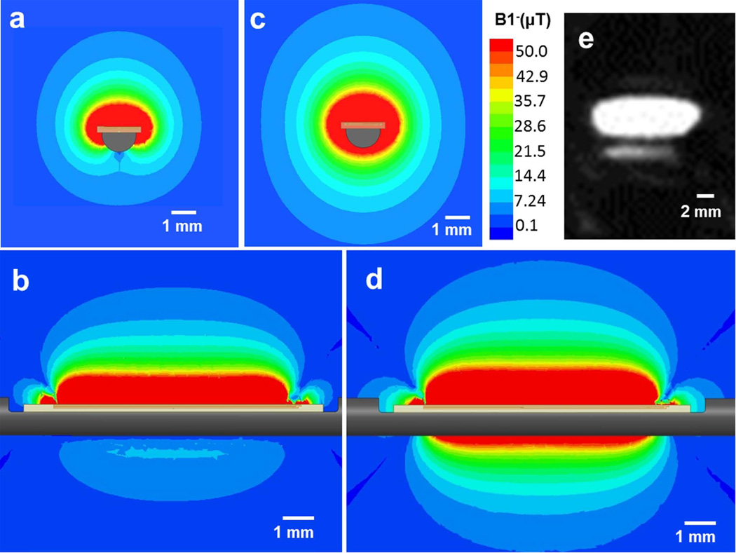
Figure 3.
(a) Axial view (cross-section of the stylet) and (b) sagittal view (along and perpendicular to the shaft) of the B1− EM field simulation with an 8-mm-long micro-coil attached to a metallic stylet. (c) Axial view and (d) sagittal view the B1− EM field simulation with the same micro-coil attached to an insulating stylet. Note that the lobe pattern obtained with the metallic substrate is far smaller than that with the insulating substrate. (e) A high-resolution MR image of a tracking coil mounted on the metallic stylet, acquired with a 3D Turbo Spin Echo sequence. The imaging slice was oriented in the sagittal plane along the active stylet shaft. It demonstrates that strong signal is obtained ~5 mm away from the needle surface.

