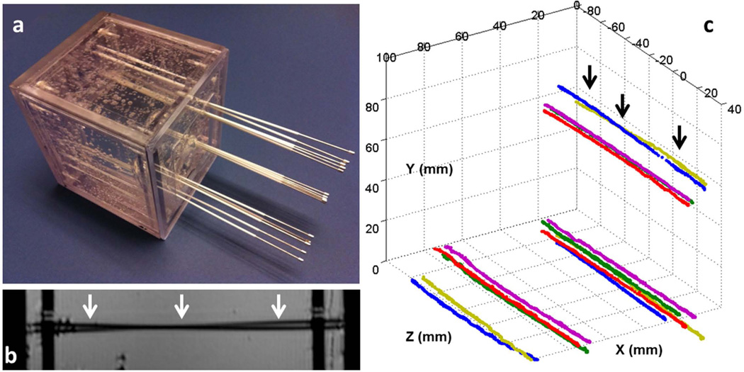
Figure 6.
(a) Gel phantom with fifteen catheters inserted. All the catheters initially contained conventional stylets within them. A set of five stylets were placed into each of the three corners of the cubic phantom. In each set, three stylets were almost parallel to each other, while two crossed each other. (b) A high-resolution sagittal MR image of the phantom. The two black lines (white arrows) show two catheters that cross each other, which is difficult to identify because it can also represent two touching bent catheters. (c) Fifteen stylet trajectories acquired by capturing the tracked tip position continuously during active stylet pull-out. In all cases, the active tracking system generated stable tracking signal profiles and resolved the trajectories well. Note that two stylets at each of the three corners crossed each other, with the two at the upper corner (black arrows) also shown in b.

