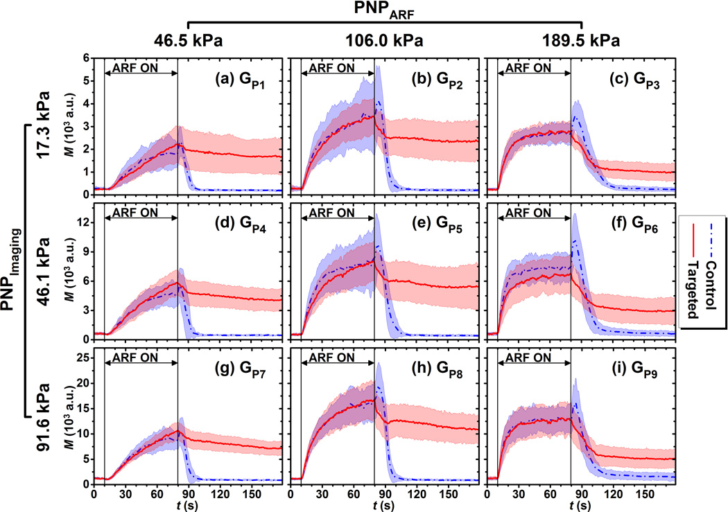
Figure 3.
Signal magnitude curves in regions of adherent microbubbles in control (blue) and targeted (red) phantom channels at different acoustic conditions listed in Table 1. (a) GP1, (b) GP2, (c) GP3, (d) GP4, (e) GP5, (f) GP6, (g) GP7, (h) GP8, (i) GP9. Blue dash-dot and red solid lines indicate the mean values from 10 trials. Light color shadows indicate the corresponding error bars at the range of [mean ± standard deviation]. Different y-axis scales used to make comparison between curve shapes easier.

