
Figure 10.
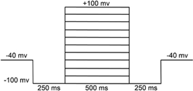
Corresponding step protocol used to elicit current trace. To observe the current–voltage relationships, step pulses were generated from a holding potential of −40 mV to test potentials from −100 to +100 mV with 20 mV increments. To record the greater magnitude of pulse-induced currents, the −100 mv conditioning pulse was applied before and after test potentials.