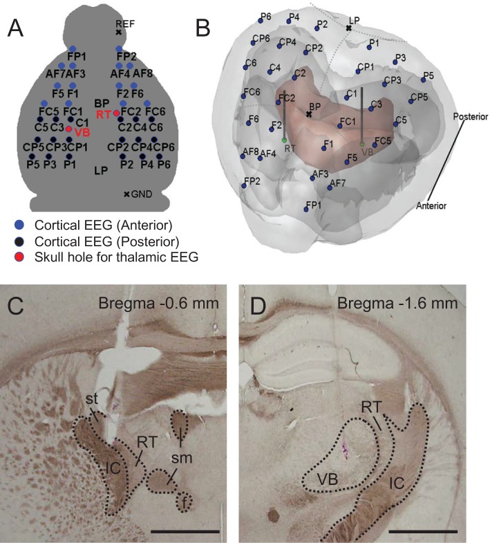
Figure 1.
EEG and LFP montage and histological verification. (A) Cortical EEG and thalamic LFP montage (blue filled circles for anterior channels, black filled circles for posterior channels, and red filled circles for two thalamic regions; BP, bregma; LP, lambda; REF, reference; GND, ground). (B) Visualization of electrode locations together with corresponding anatomical details through the transparent surface. 3D MRI brain surface rendering was carried out by using the rendering software. Mouse MRI was downloaded from open database of the Magnetic Resonance Microimaging Neurological Atlas Group (http://brainatlas.mbi.ufl.edu/Database/.; accessed January 8, 2014). The outer surface is the surface of neocortex, and the red surface indicates the thalamus. The olfactory cortex and cerebellum are not included in this image. The blue dots represent the positions of 32-channel EEG, and green dots represent the positions of RT and VB LFP electrodes. (C) and (D) are histological verification of electrode tips on RT and VB, respectively. Horizontal bars for 1 mm. IC, internal capsule; st, stria terminalis; RT, thalamic reticular nucleus; sm, stria medullaris of the thalamus; f, fornix; VB, ventrobasal nucleus.

