
Figure 1.
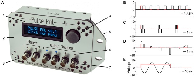
Pulse Pal is a programmable pulse train generator. (A) Pulse Pal front view, illustrating front panel features. 1: High contrast oLED screen permits programming with thumb joystick for stand-alone use. 2: Custom laser-cut acrylic enclosure. 3: Two optically isolated digital trigger channels. 4: Thumb joystick. 5: Rack-mount wing. 6: Channel activity indicators illuminate when channel voltage is not the set resting voltage (i.e., during a pulse). 7: Each of four analog output channels can be programmed with independent pulse trains and linked to either trigger channel. (B–E) Example pulse trains in black, acquired with an oscilloscope (see methods). Trigger voltage traces are shown in red. (B) A Pulse Pal output channel configured to deliver a train of 5 V, 100 µs square pulses with 200 µs intervals. (C) A train of biphasic +/−5 V 100 µs pulses, gated programmatically to produce pulse bursts. Trigger channel mode set to “toggle” aborts the ongoing pulse train in mid-burst when a second pulse arrives. (D) A train of 500 µs pulses with custom onset times and voltages. Pulses with consecutive onset times merge to form more complex waveforms (right). (E) A train of consecutive 100 µs pulses, whose voltages and onset times were configured to generate one period of a sine waveform. The output channel uses “loop mode”, to repeat the sine waveform until a parametrically specified pulse train end. The trigger channel mode was set to “pulse gated” mode, to abort the pulse train when its voltage returned low.