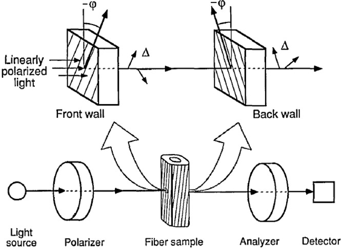
Fig 2.

The front and back of the cell wall are described as linear retarders with the same relative retardation and opposite angles of orientation. Adapted from Ye et al. (1994). This set-up corresponds to the modified Herzog test set-up except that here an additional 530 nm full wave compensator is inserted between the polarizer and analyser.
