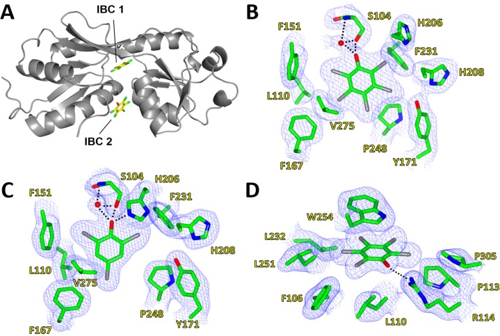
Figure 4.
Inducer-binding cavities (IBC) of PcpR. (A) Relative locations of IBC1 and IBC2; (B) PCP binding cavity 1. 2Fo–Fc map showing coverage of PCP in IBC1 under the hinge between RDI and RDII; (C) 2,4,6-TCP binding cavity. 2Fo–Fc map showing coverage of 2,4,6-TCP in IBC1; and (D) PCP binding cavity 2. 2Fo-Fc map showing coverage of PCP in IBC2 between α1 of RD1, α9 of RD2 and a flexible loop contributed by the adjacent monomer. These figures were generated using CCP4MG Version 2.9.0 [19].

