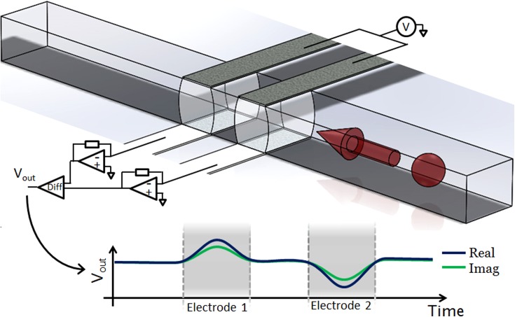
FIG. 1.
Illustration showing the structure and operation of the impedance cytometer. The device consists of two sets of parallel facing electrodes (30 μm wide separated by 50 μm) fabricated inside a microfluidic channel (40 μm wide and 30 μm high). Cells suspended in an electrolyte are driven through the channel by pressure driven flow. An AC voltage is applied to the top two electrodes and the difference in current flowing through the bottom two electrodes is measured using a custom detection circuit. Also shown is the idealised differential signal seen when a particle passes through the centre of the device.

