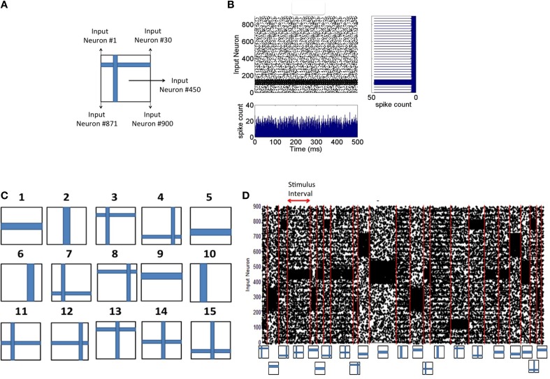
Figure 2.
Spike input encoding at the source layer of the network. (A) An input pattern in the form of 2-D array of pixels is presented to the source neurons of the network that are linearly arranged. See Materials and Methods section for details of spike encoding. (B) The spikes generated during the presentation of the example in (A) for 500 ms duration is shown here. The firing rate at any given time (the bottom subplot) is approximately the same showing no undue bias introduced in the spikes that are fed to the source neurons. The linear arrangement of the source neurons results in the spike frequency plot (shown on the right) for the given input pattern computed for a duration of 500 ms. (C) Input patterns of the training set consists of P = 15 “flag” patterns where each pattern is a binary image array of 30 × 30 pixels. (D) An example sequence of input patterns after spike encoding at the source neurons is shown here. The duration of the presentation of each pattern varies and is chosen from an exponential distribution with a mean of 30 ms. Red lines demarcate the shift from one training pattern to another. The training patterns are selected from the set of 15 in a random order. The plot shows a total duration of 1800 ms with 10% of the source neurons injected with noise throughput the sequence.

