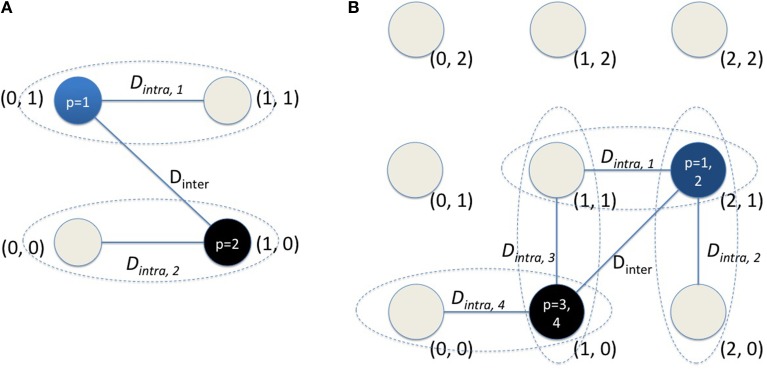
Figure A1.
The details of DI computation for two different examples are shown here. (A) The readout code for the first example uses M = 2 and C = 2 as visualized here. Each node represents one of four possible states. There are a total of input patterns (P = 2) for this example. (B) The readout code for the second example uses M = 2 but C = 3 as visualized here. Each node represents one of 9 possible states. There are a total of 4 input patterns (P = 4) for this example.

