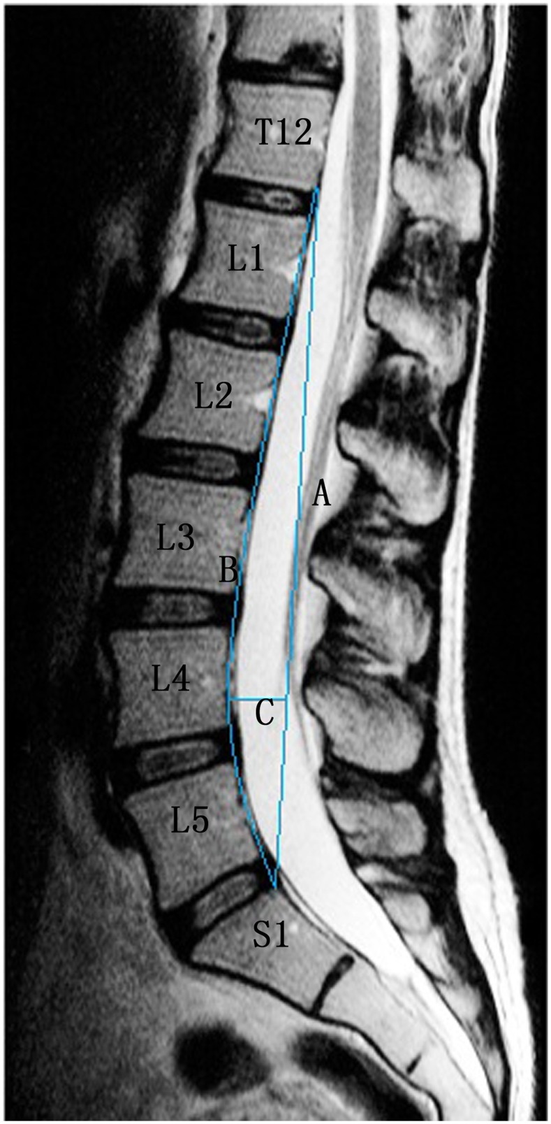
Figure 7. Seze method.
A straight line is drawn from the superior posterior aspect of the odontoid process of the T12 vertebra to the posterior inferior aspect of the body of the S1 vertebra named line A. Another line is traced along the posterior aspect of the intervening lumbar vertebral bodies named line B. The third line intersects A perpendicularly at the point of greatest distance between lines A and B. The length of C recorded in millimeters is the depth of the lumbar lordosis.

