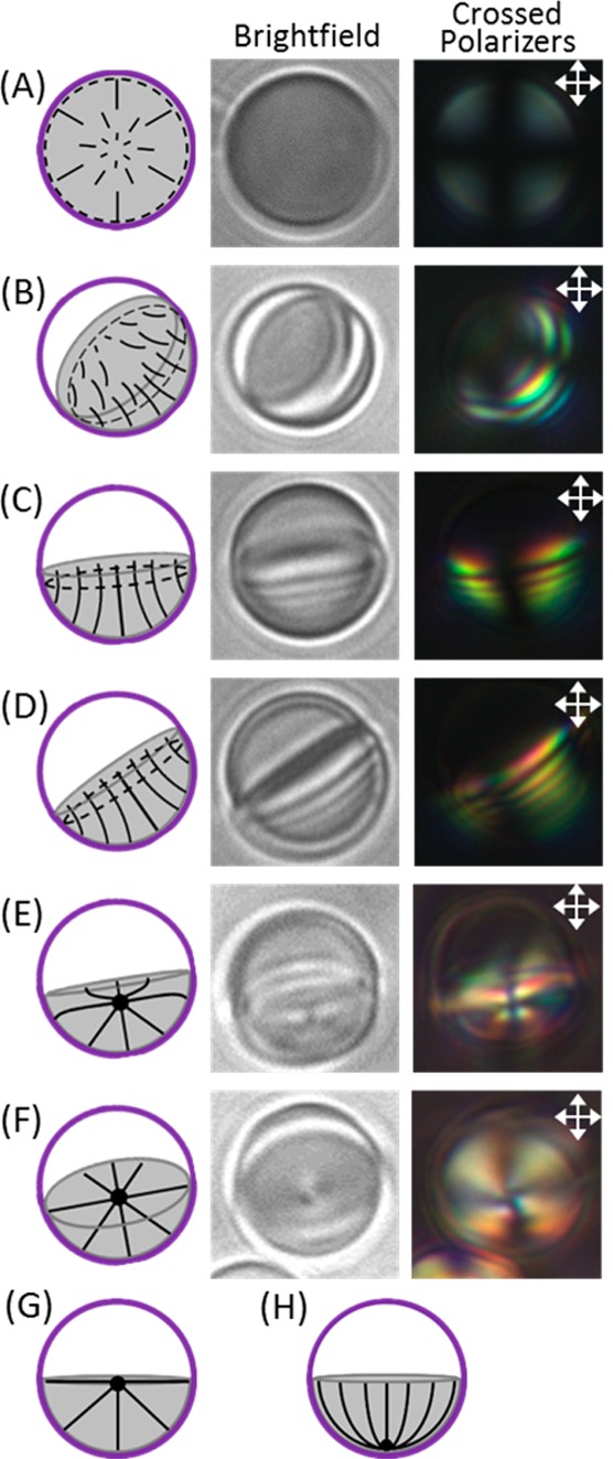
Figure 8.

Schematic director profiles (left column) with corresponding bright-field (middle column) and polarized light (right column, crossed polarizers indicated by white arrows) micrographs of (A) top, (B) tilted, and (C, D) side views (at different angles with respect to the polarizer/analyzer) of hemispherical LC droplets contained within DADM capsules in 0.25 mM SDS. (E, F) Side views at different angles of hemispherical LC droplets in 1 mM SDS. (G, H) Schematics show possible director configurations for inhomogeneous boundary conditions.
