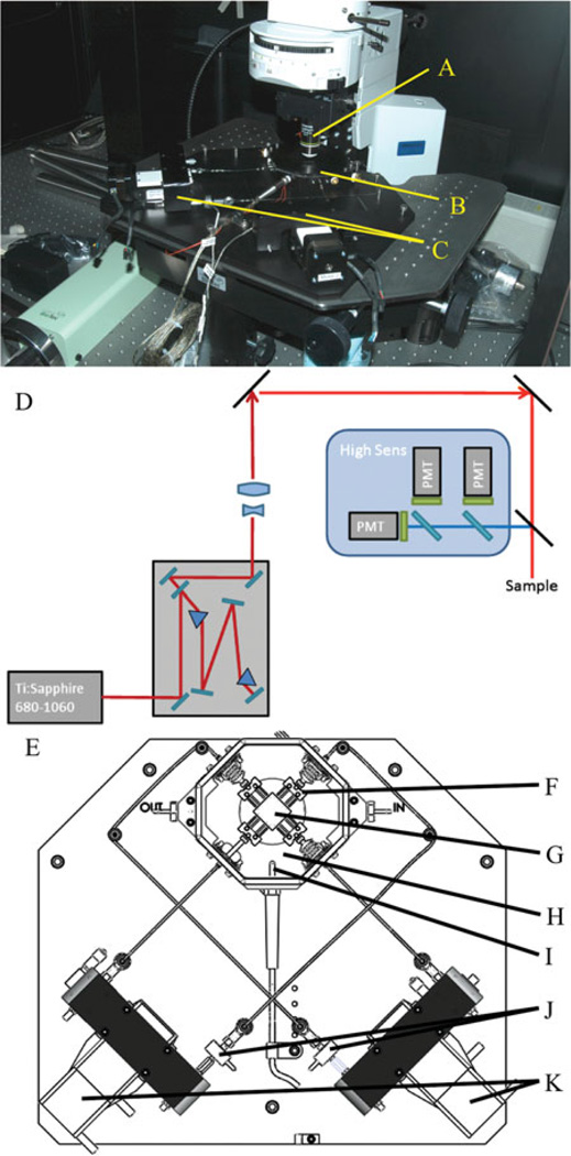
Figure 1.
Microscope set up. The MOD is placed on the x, y stage and positioned so the cover slip in the lid of the bath is placed beneath the objective lens (A). B: Testing bath with a sample inside. C: Motors of the MOD. D: The microscope optical layout used in this study. E: Arrangement of the pulling scheme for the MOD (top-down view). F: The spindle the sample is attached to (to allow free shear in the sample). G: A sample sutured in place. H: The bath. I: The thermocouple. J: The load cells attached to the rod end and the linear stages. K: The linear stages. Not shown are the heaters under the bath.

