
Figure 1.
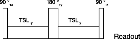
Spin lock pulse sequence used to obtain T 1ρ weighted images. The pulse sequence consists of 2 continuous RF pulses with opposite phase to compensate for B1 variations, and a refocusing pulse between the spin-locking halves to compensate for B0 errors, followed by the readout.