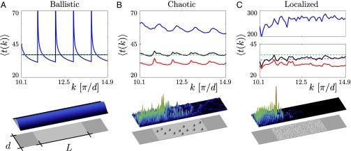
Fig. 3.

Total average dwell time (black line), transmission delay time (blue line), and reflection delay time (red line) for (A) ballistic scattering through a clean waveguide as well as for (B) chaotic scattering through a disordered waveguide with 13 circular obstacles of radius and (C) Anderson localized transport through a disordered waveguide with 211 obstacles of (see Supporting Information for a definition of transmission and reflection delay times). The geometrical parameters were chosen such that all three waveguides have the same width d and the same effective scattering area . The wavenumber was scanned between and in all three cases. For the clean waveguide in A the transmission is perfect, and thus the reflection times are strictly zero. The average for the total dwell time (black line) is taken here over the entire wavenumber interval shown and coincides with the estimate of Blanco and Fournier (4), (green dashed line). For the disordered systems in B and C the averages were taken over (B) 250 and (C) 2,500 different random configurations, respectively. Whereas for the chaotic scattering case (B) the results for the average dwell time agree well with the random walk prediction (dashed green line), a systematic deviation is observed for the case of strong disorder (C). Here, very good agreement is found with the estimate for the average dwell time according to the corrected Weyl estimate, Eq. 8 (purple dashed line). (Lower) The intensity of wave functions injected in the lowest-order mode is shown for a specific configuration of scatterers (see gray spheres) embedded in the scattering area (light gray domain in the middle). The flux is incoming from the left and can be transmitted (to the right) or reflected (to the left) through the perfect waveguides attached on both sides (see dark gray areas).
