
Figure 7.
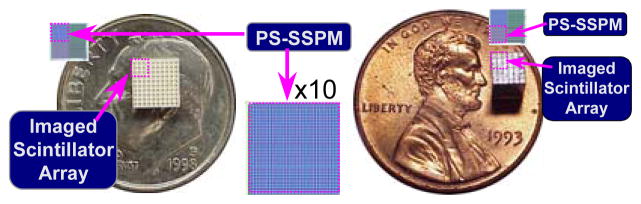
(left) Segmented CsI scintillation crystal used to characterize the “APD analog” PS-SSPM detector, placed on dime for scale. Only 3×3 scintillation segments sit atop of the PS-SSPM detector, as indicated by the dashed boxes. A magnified image of the SSPM device is labeled “×10”. The segmented LYSO scintillation crystal (right) used to characterize the “row-column” PS-SSPM detector. As with the CsI, only 3×3 scintillation segments sit atop of the PS-SSPM device, which is on of the four devices on the chip.