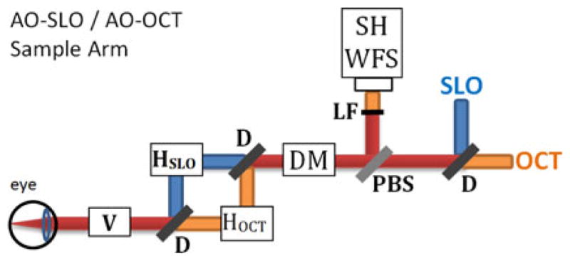
Fig. 5.

Illustration of AO-OCT/AO-SLO instrument sample arm, showing scanning mirror arrangement and some adaptive optics details. Yellow rays—AO-OCT path; green rays—AO-SLO path; red rays—common path for both systems. HSLO —SLO horizontal scanner; HOCT —OCT horizontal scanner; V —Vertical Scanner; D—dichroic mirror, DM—deformable mirror for adaptive optics, PBS—pellicle beam splitter, LF—low-pass optical filter, SH WFS—Shack-Hartmann wavefront sensor.
