Abstract
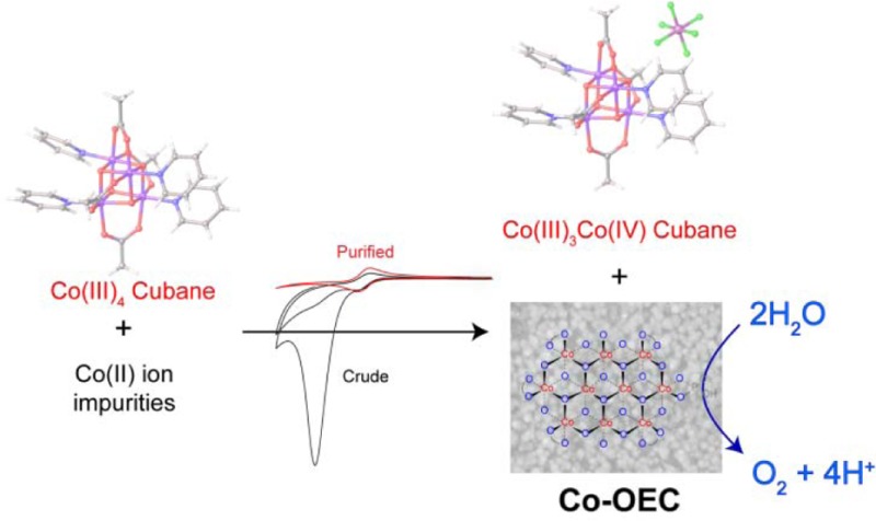
The observed water oxidation activity of the compound class Co4O4(OAc)4(Py–X)4 emanates from a Co(II) impurity. This impurity is oxidized to produce the well-known Co-OEC heterogeneous cobaltate catalyst, which is an active water oxidation catalyst. We present results from electron paramagnetic resonance spectroscopy, nuclear magnetic resonance line broadening analysis, and electrochemical titrations to establish the existence of the Co(II) impurity as the major source of water oxidation activity that has been reported for Co4O4 molecular cubanes. Differential electrochemical mass spectrometry is used to characterize the fate of glassy carbon at water oxidizing potentials and demonstrate that such electrode materials should be used with caution for the study of water oxidation catalysis.
Introduction
The design of efficient water oxidation catalysts (WOCs) based on nonprecious materials remains an important challenge for achieving a clean and sustainable solar fuels-based energy economy.1−3 We have previously shown that active WOCs can be formed by anodic electrodeposition of metal-oxides from neutral and near-neutral buffered aqueous solutions of cobalt,4,5 nickel,6,7 and recently, manganese.8,9 In particular, the cobalt oxygen-evolving catalyst (Co-OEC) has been studied in detail, resulting in an understanding of the electrochemical kinetic mechanisms of its formation,10 catalysis,11 and charge transport.12 The structural and electronic properties of Co-OEC have been clarified using XAS,13 X-ray PDF,14,15 EPR,16 and X-ray GID.17 These studies have revealed that the electrodeposited catalyst films comprise molecular to nanoscale-sized metalate clusters composed of edge-sharing CoO6 octahedra with a mixed valence Co(III/IV) resting state.
The development of soluble molecular WOCs based on Co18−21 as well as other transition metals, such as Ir,22 Ru,23 Cu,24 and Fe25 have also been a subject of intense focus. Molecular WOCs are attractive research targets because they provide a tractable means to characterize catalytic mechanisms and to identify reactive intermediates, thus forming the basis for the continued development of new WOCs. However, the true identity of the active catalyst must be clarified prior to a detailed interrogation of the WOC mechanism. Indeed, some molecules that were thought to be WOCs have subsequently been shown to be precursors of heterogeneous or colloidal materials, which are the active catalysts.26−29 Proper catalyst identification is especially challenging for the study of molecular cobalt WOCs because extremely small amounts of Co-OEC may be produced from the decomposition of the molecular catalyst.30,31 An exemplar of this challenge is the all-inorganic cobalt polyoxometalate [Co4(H2O)2(PW9O34)2]10– (Co4POM), which was suggested as a WOC.32 Re-examination of the molecule showed that electrochemically driven oxygen evolution arose from the formation of Co-OEC on glassy carbon (GC) electrodes at 1.1 V vs Ag/AgCl.30 Because the Co4POM was unstable at higher potentials, water oxidation activity could not be conclusively attributed to the Co4POM, as opposed to its role as a molecular precursor to Co-OEC.33 The Co4POM has now been suggested to exhibit water oxidation activity but under specific photochemical conditions where Ru(bpy)33+ is the oxidant.34,35
Against this backdrop, cubane Co4O4 clusters, such as Co4O4(OAc)4(Py)4, (1, Figure 1), have come under investigation as a class of molecular cobalt complexes that are potential WOCs.36−40 We had previously investigated 1, first synthesized by Das and co-workers,41 and a related Co4O4 cubane of Christou,42 in order to gain valuable insights into the electronic characteristics and proton-coupled electron transfer (PCET) behavior of Co(III/IV) in a Co-OEC environment.43,44 The structure of 1 has been previously reported (Figure S1, Supporting Information);41 the crystal structure of the oxidized cubane 1+ was known as a perchlorate salt45 and is now obtained as a PF6– salt, as shown in Figure 1. In our studies, we did not find any evidence that these cubanes were active WOCs. Motivated by the recent reports to the contrary36−39 and subsequent computational work outlining a detailed mechanistic pathway for 1 as a WOC,46 we renewed our investigation of these molecules.
Figure 1.
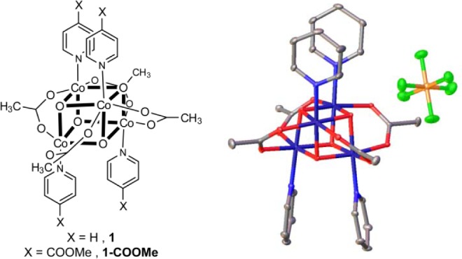
(left) Molecular structure of Co4O4 cubane structure 1 and (right) thermal ellipsoid representation at the 50% probability level of the one-electron oxidized cubane, 1[PF6]. Hydrogen atoms and an acetonitrile molecule have been omitted for clarity. Atoms are color-coded: gray (carbon), blue (nitrogen), red (oxygen), dark blue (cobalt), green (fluorine), and yellow (phosphorus).
Herein, we report that a Co(II) impurity in as-synthesized cubane 1 is primarily responsible for the reported catalytic water oxidation activity. We present a series of experiments that are useful for determining whether a small amount of a Co(II) impurity may lead to formation of a heterogeneous WOC. We further emphasize the utility of differential electrochemical mass spectrometry (DEMS) for clarifying how anodic potentials affect the decomposition of glassy carbon electrodes, which are commonly used in the study of WOCs. The reported experiments are aimed at establishing a standardized approach to evaluate the presence of Co(II) impurities in molecular complexes under investigation as water oxidation catalysts.
Results
Synthesis
We synthesized and isolated 1 by precisely following the one-pot procedure developed by others.36,39 Despite satisfactory elemental analyses for 1 (Table S1), we determined that this as-synthesized material, which was isolated by concentrating a dichloromethane (DCM) extraction, was not pure. The presence of impurities was indicated by the observation of many small peaks in the 1H NMR spectrum (Figures 2 and S2–S4) and by the presence of slowly moving bands that eluted behind the product band on a silica thin layer chromatography (TLC) plate (Figure S5). On the basis of the TLC result, purification of the compound was performed by column chromatography on silica, eluting with a gradient of 2–10% MeOH in DCM. Along with the slowly moving green bands, a red coloration was consistently observed at the top of the column. A comparison of 1H NMR spectra for crude (i.e., as-synthesized) and purified 1 is shown in Figure 2. Several peaks that are observed in the aromatic region in the NMR of the crude sample are absent in the NMR of the purified sample. Molecular impurities are also indicated by many peaks in the m/z range of 300–700 in the ESI-MS of crude 1; these peaks are absent in the purified sample (Figure S6). A structural variant, 1-COOMe, was also synthesized according to Das’ original procedure;41 the final product was isolated by precipitation and filtration. No diamagnetic impurities were detected in the 1H NMR spectra of the precipitated 1-COOMe. However, to remove possible paramagnetic impurities, the precipitated 1-COOMe was subject to further purification by chromatography. Interestingly, the same 1H NMR spectrum was obtained for precipitated and chromatographed 1-COOMe (Figure S7), though the former was observed to have impurities that were not removed by precipitation.
Figure 2.
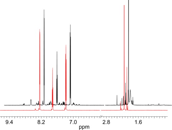
A comparison of the 1H NMR spectra of (black line) 10 mM crude 1 and (red line) 10 mM pure 1 in D2O.
Electrochemistry
The reported water oxidation activity of 1(36,39) could not be replicated using purified samples. Figure 3 compares the CVs of crude and purified 1 (0.852 mg/mL, 1 mM assuming 100% purity). The catalytic current, peaking at 1.3 V (all potentials are referenced to Ag/AgCl), in the crude sample is consistent with the WOC activity that has been previously reported of 1 in the presence of proton accepting electrolytes. However, a similar catalytic wave in the purified sample is completely absent; only a reversible Co(III)3Co(IV)/Co(III)4 couple centered at E1/2 = +1.05 V is observed. Interestingly, the catalytic current detected with the crude sample is only prominent in the first scan of the CV. A similar behavior is observed for 1-COOMe where precipitated samples exhibit a large catalytic current in the CV and chromatographed samples show only the reversible Co(III)3Co(IV)/Co(III)4 couple, as shown in Figure S8. The E1/2 of the reversible couple is at a more positive potential than for 1, due to the electron withdrawing nature of the methyl ester substituents on the pyridine ligands.
Figure 3.
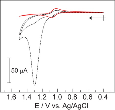
Background corrected CVs of crude (black dotted) and purified (red solid) samples of 1 (0.852 mg/mL) in 0.2 M KPi buffer, pH = 7. Two scans are presented for the crude sample demonstrating the loss of activity upon the second scan. Crossed arrow indicates initial point and direction of scan.
The electrochemistry of 1 was also investigated in carbonate buffer at pH = 7. The crude sample also showed a catalytic current (Ep = ∼1.4 V, Figure S9), which was absent in the purified sample. The only observed difference between the CVs in carbonate and phosphate electrolyte is that the catalytic peak current of the crude sample occurs at a more positive (∼80 mV) potential in carbonate electrolyte.
To confirm that the catalytic current in the crude sample was associated with the oxygen evolution reaction, electrochemical oxidation was performed in a DEMS experimental setup, which allows for the immediate and simultaneous detection of all gaseous products formed at the electrode surface.47 The catalytic current from an unpurified sample shown in the red trace of the top of Figure 4A is accompanied by the production of O2, as shown in the middle panel of Figure 4A. Purified 1 and 1-COOMe were also investigated using DEMS under the identical conditions employed for that of the crude sample. As shown in the top panels of Figure 4B,C for purified 1 and 1-COOMe, respectively, the Faradaic current density decreases by over an order of magnitude from that of the crude sample. The waveform of the CVs in Figure 4 are different than those of CVs taken on stationary GC electrodes (e.g., Figure 3, red trace) owing to the flow conditions of the DEMS experiment; similar waveforms are observed, for instance, at rotating disk electrodes where there is forced solution flow across an electrode surface.48 The signal from the mass channel of O2 for the purified samples (middle panels in Figure 4B,C) shows no O2 production for applied potentials below 1.4 V; at potentials of 1.4 V or greater, an extremely small amount of O2 is observed (pA intensities as opposed to nA intensities of crude samples). We note that for all three samples, the mass channel of CO2 exhibits a sizable signal when the electrode potential surpasses ∼1.2 V. The high level of evolved CO2 is observed even in the background scans of blank GC electrodes (black lines in the bottom panels in Figure 4A–C).
Figure 4.

DEMS experimental data for three samples: (A) crude 1-COOMe, (B) purified 1 and (C) purified 1-COOMe. Top panels display the Faradaic current density vs potential; middle and bottom panels display the current collected for mass channels 32 (O2) and 44 (CO2) m/z, respectively. Red lines are representative data from the samples, and black lines are the data from the corresponding blank GC electrodes.
We sought to place a limit on the level of O2 produced by the cubane cluster within the error of our measurements. The middle panel of Figure 4B indicates that there is a small but non-negligible amount of O2 produced in purified samples of 1 at applied potentials >1.4 V. We therefore wished to quantify the amount charge passed with the current associated with the slight downturn in the red CV trace at potentials above 1.4 V in Figure 3. Three separate voltammograms (using three independently prepared GC electrodes) were collected with a sample of purified 1 (black traces in Figure S10b–d). A simulated CV (Figure S10a) was subtracted from the background corrected raw data to remove the current that is due to the reversible Co(III)3Co(IV)/Co(III)4 couple, thus leaving only the current that may be attributed to oxygen evolution (red traces in Figure S10b–d). From these data, the average current density was 0.11 ± 0.04 mA/cm2 at 1.5 V. Assuming that all of this current leads to the production of O2, then a TOF of 0.06 mol O2/mol catalyst is calculated at an overpotential of 0.89 V (see SI for details). This low current density and TOF is consistent with catalysis from ppb concentrations of Co(II) produced from decomposition of the cubane (see Discussion).
To exclude the possibility of chemistry specific to a 1:GC interaction, Pt, Au, and FTO were also employed as electrode materials. In all three cases, a similar behavior was obtained as for the GC experiments: the CVs of the crude 1 showed significant water oxidation current, which was absent in the CVs of the purified material (Figure S11).
Photochemistry
In addition to electrochemical WOC activity, photochemical water oxidation has been reported for as-synthesized samples of 1 using the Ru(bpy)32+/S2O82– sacrificial oxidant system. The photochemical assay was performed in triplicate according to the literature procedure,36 with the exception that phosphate buffer was used instead of carbonate (see SI for details). The concentration of O2 was measured for samples of crude 1, purified 1, and without added catalyst. A fluorescence-based O2 sensor was immersed into N2 purged solutions containing [Ru(bpy)32+] = 0.5 mM, [S2O82–] = 35 mM, and [1] = 0.33 mM, and the cuvettes were photolyzed with a Hg/Xe arc lamp (λexc > 400 nm). The yield of O2 over 400 s of photolysis decreased from 167 ± 15 μM for the crude samples to 31 ± 6 μM for the purified samples (Figure 5).
Figure 5.
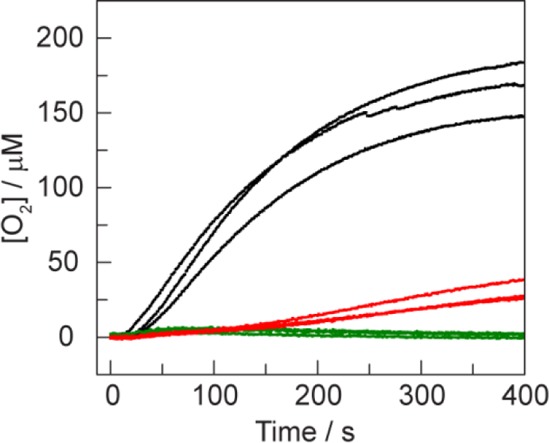
Solution [O2] measurements during illumination of crude samples of 1 (black), purified 1 (red), and without added 1 (green). Photochemical reactions were performed in the presence of 0.5 mM Ru(bpy)32+, 35 mM Na2S2O8, and 100 mM KPi pH = 7 buffer. The concentration of crude and purified 1 was 0.33 mM, assuming 100% purity for the crude material.
Identification and Quantification of Impurities
To identify and quantify the impurity found in the crude samples of 1, a series of spectroscopic and electrochemical experiments were performed. The EPR spectrum of a solid sample of crude 1 reveals a broad paramagnetic signal over the range g = 10 to 2, which is absent in the purified sample (Figure S12). This signal is consistent with a paramagnetic Co(II) species.16 To confirm the presence of a Co(II) impurity, EDTA was titrated into a CV solution of the crude sample. Figure 6 shows the CVs for the addition of EDTA (0–0.5 mM) into a 2 mM solution (assuming 100% purity) of crude 1 in 0.2 M KPi pH = 7. Nearly complete suppression of the catalytic current was observed at 0.5 mM EDTA addition. As a control, a 50 μM solution of purified 1 was treated with 10 mM EDTA in 0.2 M KPi at pH = 7 for 1 h, and no changes in absorbance were observed (Figure S13), confirming that 1 is kinetically stable in the presence of EDTA. The CV wave of the Co(III)/Co(IV) couple of purified 1 with addition of EDTA (Figure S14) is fully reversible, indicating that 1+ is also stable to EDTA on the time scale of the CV experiment.
Figure 6.
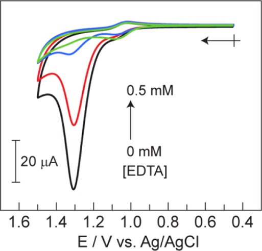
CVs of 2 mM (assuming 100% purity) crude 1 and [EDTA] = 0 (black), 0.10 (red), 0.25 (blue) and 0.50 (green) mM in 0.2 M KPi (pH = 7). Arrow and cross indicates the initial point and direction of scan.
The amount of Co(II) introduced by dissolving the crude preparation of 1 in aqueous media could be quantified by applying 31P NMR line broadening analysis, which we previously employed to quantify the self-healing properties of Co-OEC.10 A calibration curve was constructed by adding increasing amounts of a 1:1 mixture of Co(OAc)2:pyridine to a 0.5 mM solution (0.426 mg/mL) of purified 1 in 0.2 M KPi buffer (Figure 7, see SI for experimental details). This calibration curve was used to determine the amount of Co(II) in batches of crude 1. Although CV experiments were performed with 1 at a concentration of 0.852 mg/mL, at this concentration of crude 1, the broadening of the phosphate signal is too great to construct a calibration curve over a wide enough range. Thus, we performed 31P NMR line broadening experiments at half the concentration used for CV experiments. Figure 7 shows the 31P NMR signals of phosphate upon dissolving 0.426 mg/mL of crude 1 for three separately prepared batches. Per the calibration curve, we determine that the Co(II) ion concentration in solution is [Co(II)] = 0.086 ± 0.004 mM, 0.091 ± 0.008 mM and 0.065 ± 0.006 mM for samples (c), (d) and (e), respectively ([Co(II)]avg = 0.08 ± 0.01 mM). Translating this result to the concentrations used for CV experiments, a sample of 0.852 mg/mL of crude 1 introduces an average concentration of [Co(II)] = 0.16 ± 0.02 mM into solution.
Figure 7.
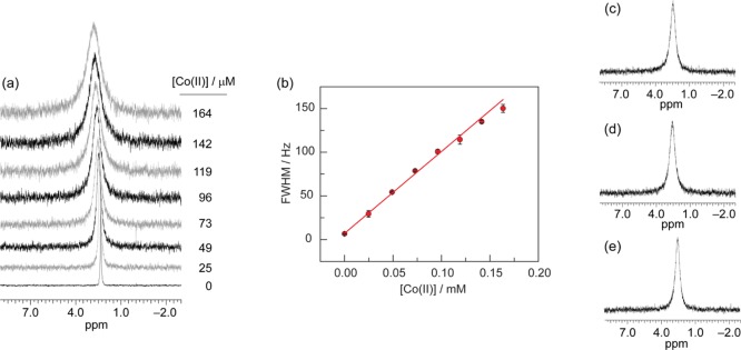
(a) 31P NMR spectra of the phosphate signal of a 0.5 mM solution (0.426 mg/mL) of purified 1 in 0.2 M KPi (pH = 7) with added Co(II) at the indicated concentrations. (b) The measured full-width at half-maximum (fwhm) of the phosphate 31P NMR signal is linearly dependent on the concentration of added Co(II). The equation of the linear calibration curve is fwhm = {(936 ± 8) × [Co(II)]} + (7.2 ± 0.4). (c–e) 31P NMR spectra of the phosphate signal for three separate batches of 0.426 mg/mL of crude 1 in 0.2 M KPi at pH = 7. Using the calibration curve of (b), the amount of line broadening corresponds to a Co(II) concentration of 0.086 ± 0.004 mM, 0.091 ± 0.008 mM, and 0.065 ± 0.006 mM for samples (c), (d) and (e), respectively.
The results of the 31P NMR experiments were confirmed by an electrochemical titration, in which [Co(II)] was correlated with the catalytic current observed by CV (Figure S15). With increasing [Co(II)], the peak current of the catalytic wave at 1.3 V increases linearly. A calibration curve was again constructed and used to assess [Co(II)] in the three batches of crude 1 at the concentration used for CV experiments. The results of this assay shows excellent agreement with the 31P NMR experiment, albeit with larger error bars, giving 0.153 ± 0.019 mM, 0.178 ± 0.020 mM, and 0.120 ± 0.016 mM for the three samples, with a [Co(II)]avg = 0.15 ± 0.03 mM.
Because of the insolubility of Co3(PO4)2 in aqueous media, the measured Co(II) concentration could be diminished due to loss of cobalt in the form of a Co3(PO4)2 precipitate. However, at these low [Co(II)], precipitation of Co(II) by phosphate is negligible due to the slow kinetics of formation of the Co3(PO4)2 on the time scale of the electrochemical or photochemical experiments, which take minutes to complete. To experimentally verify that no Co3(PO4)2 formed under our experimental conditions, a 0.15 mM solution of a 1:1 mixture of Co(OAc)2:pyridine in the presence of 0.2 M KPi at pH = 7 was monitored by 31P NMR line broadening over a 4 h period (Figure S16). The 31P NMR spectrum establishes that the concentration of Co(II) in solution does not significantly decrease over this time period.
The 31P NMR line broadening experiment is also a sensitive measure of compound stability. Solids of purified 1 can be stored on the benchtop for at least 25 days without decomposition. The 31P NMR line broadening analysis of 0.5 mM 1 in 0.2 M KPi buffer solution shows that the presence of Co(II) ions after 25 days is negligible (Figure S17). In addition, comparison of the 1H NMR spectra of 1, hours after purification and after 25 days are identical (Figure S18).
Characterization of Electrode Surface
Since crude 1 introduces Co(II) into the solution, we would expect that at anodic potentials, Co-OEC will be deposited. Indeed, bulk electrolysis of a 1 mM solution of crude 1 at 1.2 V for 5 min resulted in the deposition of Co-OEC material on the electrode surface, which was readily observed by scanning electron microscopy (SEM) and energy dispersive X-ray spectroscopy (EDS) (Figures S19a and S20a, respectively). Bulk electrolysis of the crude sample at a higher potential of 1.4 V results in significantly less Co-OEC detected on the electrode surface (Figures S19c and S20c), despite more charge being passed (Figure S21). Per the DEMS experiment, current is redirected from water splitting (O2 production) to degradation of the GC electrode (CO2 production at higher potential).
Although bulk electrolysis performed over 300 s of a purified sample at 1.2 V resulted in an EDS spectrum that is indistinguishable from that of a blank sample (Figure S20b,d), the SEM images of the pure and blank samples showed a subtle difference. The density of light contrast material was increased in the pure sample as compared to that of the blank sample. We therefore pursued further characterization of the electrode surface by XPS analysis, which is more selective to analysis of surface materials than EDS. A comparison of high-resolution Co 2p XPS spectra of crude, pure, and blank GC electrodes after 300 s of bulk electrolysis at 1.2 V is shown in Figure S22. A trace signal at the Co 2p3/2 peak of the pure sample is barely distinguishable over background, whereas a large Co 2p3/2 signal is observed for electrodes removed from bulk-electrolyzed solutions of crude 1.
Discussion
As-synthesized samples of 1 contain significant amounts of impurities in two forms. The many aromatic peaks in the 1H NMR spectra of crude 1 (Figure 2) and the slowly eluting bands on TLC plates are likely Co(III) clusters of smaller nuclearity, which are known to be stable compounds.49 Of greater significance, as demonstrated by EPR spectroscopy (Figure S12), electrochemical measurements in the presence of the ion scavenging EDTA (Figure 6) and 31P NMR line broadening analysis (Figure 7), a Co(II) impurity is present in crude samples of 1. Electrochemical titration experiments and 31P NMR line broadening experiments quantify significant amounts of Co(II) in as-synthesized preparations of 1. Repeated experiments on different batches of as-synthesized 1 show that the concentration of Co(II) is 16% of the expected concentration of the cubane molecule, 1. Because the Co(II) impurity is soluble in DCM, the ligation of the Co(II) ion likely involves solubilizing organic groups, such as the acetate or pyridine reactants of 1, as salts of Co(II) with outer-sphere anions, such as acetate or nitrate, are unlikely to have significant solubility in DCM. Ligation of the solubilizing groups appears to be sufficiently weak that Co-OEC is easily formed (vide infra). As a cautionary note, the absence of line broadening in the 1H NMR spectra of 1 does not provide sufficient evidence that Co(II) is not present in solution.36 The lack of significant line broadening in the 1H NMR spectra upon titrating 1:1 Co(OAc)2:pyridine into a sample of purified 1 (Figure S23) indicates that this is not a sensitive measure of paramagnetic impurities, presumably because 1 (a neutral, weakly basic molecule) does not interact significantly with the Co(II) ion. As Figure 7 demonstrates, the phosphate 31P NMR signal is a much more sensitive measure of the presence of Co(II) impurities. The Co(II) ion impurities do not elute on silica and thus are easily removed from 1. The same behavior is observed for 1-COOMe, where silica gel chromatography can be used to remove Co(II) impurities from as-synthesized or precipitated samples.
The Co(II) impurity acts as a source for the formation of the known water oxidation catalyst, Co-OEC. The formation of heterogeneous Co-OEC occurs from solutions of Co(II) with any proton accepting electrolyte, as long as the concentration of the electrolyte is sufficiently high to control pH.10,17 Moreover, Co-OEC will be formed from Co(II) either electrochemically or (photo)chemically as long as the potential is sufficient to oxidize Co(II) to Co(III) in the presence of electrolytes such as phosphate or carbonate. Consistent with the formation of Co-OEC, the catalytic wave in Figure 3 has the same peak potential and onset current as found for a CV of Co(II) solutions from which Co-OEC electrodeposits (Figure S24). However, unlike a well-behaved catalytic process, as is typical of Co-OEC on FTO, a peak response is observed in the cyclic voltammogram. A peak in the catalytic wave will result from either depletion of substrate or catalyst deactivation.50 Since the solvent, H2O, is the substrate, pH is maintained by a high concentration of phosphate, and current densities are low, we can safely rule out substrate depletion as the cause for the peak in Figure 3. However, a peak will result if the catalyst were to be removed from the electrode in a parasitic side reaction, or as in this case, if oxidative degradation of the electrode is significant (vide infra).
Once the impurities are removed by column chromatography, the large catalytic waves in CVs of solutions of unpurified 1 (Figure 3) and 1-COOMe (Figure S8) disappear completely. This behavior is observed on other electrode materials (Pt, Au, and FTO, Figure S11) as well. Crude 1 shows higher currents at anodic potentials than purified 1, providing further evidence that an impurity is responsible for the WOC, as opposed to spurious activity arising from a specific deleterious interaction between the cobalt cubane molecule, 1, and a GC electrode. SEM, EDS, and XPS support the formation of a heterogeneous Co catalyst, which we attribute to Co-OEC, which deposits on electrodes from bulk electrolyzed solutions of crude 1. Even in purified samples of 1, XPS indicates that indeed a small amount of cobalt can be detected on the electrode. The production of Co-OEC from purified 1 explains the small amount of O2 observed in the DEMS experiment (Figure 4B, middle panel) and the minute amount of current beyond background (Figure 3, red trace) at potentials above 1.4 V vs Ag/AgCl. If all the current at 1.5 V goes to the production of O2, the TOF at this potential would be 0.06 mol O2/mol of 1. However, only an extremely small amount of cobalt in the form of Co-OEC is needed to support the current density associated with this TOF. Using the Tafel slope and the known dependence of the exchange current density on the thickness (i.e., Co content) of films of Co-OEC,12 it was determined that only ∼70 ppb of 1, with its 4 cobalt atoms, would need to decompose to furnish enough cobalt to form Co-OEC and produce this observed current density (see SI for details of the calculation). However, we note that the amount of Co-OEC and O2 produced is negligible as compared to the Co-OEC formed from as-synthesized samples of 1.
At potentials above 1.4 V, the DEMS results show that the observed current is predominantly due to the production of CO2 when a GC electrode is used as the anode. As EDS and XPS results show, the process is so efficient at 1.4 V, that the current is largely redirected from Co-OEC production from the Co(II) impurity to oxidative degradation of the electrode. Importantly, the direct evidence of CO2 formation (Figure 4A, bottom) under conditions that thermodynamically favor the formation of Co-OEC argues against the possibility that the Co-OEC catalyst is unstable at these high potentials. If the potential is such that the rate of degradation of the GC surface is rapid, as Stracke et al.33 have noted, one cannot interpret the absence of deposited heterogeneous material after electrolysis as evidence of actual molecular catalysis, since surface catalyst will be lost upon degradation of the underlying electrode. Consistent with this argument, SEM and EDS analysis show a decrease of observable Co-OEC on the electrode for bulk electrolysis experiments performed at 1.4 V vs 1.2 V (Figures S19 and S20). Any carbon material (e.g., graphene, carbon nanotubes. etc.) may be compromised due to degradation at high anodic potentials and thus water oxidation experiments performed on carbon-based anodes should be subject to DEMS or other mass spectrometric analysis to ensure that the current is not due to electrode oxidation to CO2.
As in electrochemical experiments, removing the Co(II) impurity from photochemically driven WOC also leads to a dramatic reduction in the amount of O2 observed (Figure 5). In the photolysis experiment, persulfate (S2O82–) is used as a sacrificial oxidant to form Ru(bpy)33+ upon irradiation. The reduction potential of Ru(bpy)33+ is 1.06 V vs Ag/AgCl. At pH = 7, Co-OEC is formed from Co(II) at potentials in the range of 0.75–0.80 V vs Ag/AgCl.10 Therefore, under the conditions of the photolysis experiment, Co(II) can be oxidized to Co-OEC by Ru(bpy)33+. Furthermore, the onset of WOC by Co-OEC is 0.90–0.95 V vs Ag/AgCl, and so Ru(bpy)33+ is thermodynamically capable of driving catalyst turnover. In addition, the quenching reaction of Ru(bpy)32+ by persulfate to produce Ru(bpy)33+, also produces SO4•– as a potential oxidant, which has ample overpotential to drive water oxidation (E° ∼ 2.2 V vs Ag/AgCl).51 Thus, the major pathway giving rise to water photooxidation activity with as-synthesized 1 is consistent with the formation of Co-OEC from the in situ oxidation of Co(II) ions.
Although all photochemical studies have used as-synthesized 1,36−39 and thus water oxidation may be supported by Co-OEC, the present study shows the photochemical oxidation of purified 1 also results in the production of measurable quantities of O2 (31 ± 6 μM) over 400 s of photolysis, leading to a TOF = 2.3 × 10⁻⁴ s–1. At the potential of Ru(bpy)33+, which is within the Co(III)3Co(IV)/Co(III)4 wave (Figure 3), no O2 is produced as measured by DEMS (Figure 4B). Therefore, Ru(bpy)33+ is not a potent enough oxidant to turn over 1;37 a greater overpotential is required, if 1 is indeed a molecular catalyst under these specific photochemical conditions. As noted above, the protocol of the photochemical experiment produces the strongly oxidizing species SO4•–. This species is free not only to react directly with Ru(bpy)32+ but also to react with 1 because the concentrations of [Ru(bpy)32+] = 0.5 mM and [1] = 0.33 mM are similar. Therefore, the observed O2 emanating from the photolysis conditions used for purified 1 in Figure 5 is likely due to the interaction of 1 with SO4•–, which has a considerably more positive reduction potential than Ru(bpy)33+.
We envision photochemical WOC activity to be promoted by SO4•–. This species is capable of breaking the O–H bond (BDFE = 123 kcal/mol)52 of water directly to produce the radical, ·OH.53 We do not expect the C–H bonds of the ligands, and thus the molecule itself, to be thermodynamically stable with respect to hydrogen atom abstraction given the extreme potentials provided by the electron accepting SO4•– and proton accepting phosphate buffer species. If the cubane were to decompose, Co-OEC is a likely product of the decomposition pathway. Alternatively, computational investigations into the mechanism of WOC by 1 suggest that two oxidations of 1 to the level of Co(III)2Co(IV)2 and an acetate ligand dissociation were required prior to water attack and subsequent O–O bond formation.46 We cannot confirm if SO4•– is capable of oxidizing 1+ because the electrochemical window limits the range of potentials for investigating the behavior of 1 at potentials beyond 1.5 V. If a higher oxidized cubane is capable of water oxidation activity, it occurs at extremely high overpotentials.
Conclusion
Without purification by silica chromatography, the Co(III) oxo cubanes can be contaminated with Co(II) impurities, which are responsible for the observed water oxidation activity reported for these molecules. We have shown that an EDTA titration can be used to test for the presence of Co(II) and a 31P NMR experiment can be used for the Co(II) quantification; these experiments are more definitive than 1H NMR spectroscopy for identifying paramagnetic Co(II) impurities. Beyond Co(II) as an impurity, the use of any Co(II) complex should be assessed as an authentic WOC versus precursors for heterogeneous catalysts such as Co-OEC owing to the proclivity of Co(II) complexes to undergo rapid ligand substitution.54,55 We note that water oxidation activity of a catalyst should not depend on whether an anodic potential is supplied electrochemically or (photo)chemically for mechanisms involving outer sphere electron transfers. In instances where homogeneous and heterogeneous O2 evolution experiments do not concur, it is appropriate to consider whether other species are responsible for catalytic activity. Finally, when inspecting carbon-based electrode surfaces for the deposition of heterogeneous catalysts, care must be exercised in the choice of oxidizing potentials, as extreme values can give rise to spurious current that is associated with CO2 evolution and electrode degradation as established by DEMS.
Acknowledgments
This material is based upon work supported by the U.S. Department of Energy Office of Science, Office of Basic Energy Sciences under Award Number DE-SC0009565. EPR spectra were recorded on instruments supported by NIH Award Numbers P41 EB-002804 and EB-002026. SEM and XPS imaging was performed at Harvard University’s Center for Nanoscale Systems, a member of the National Nanotechnology Infrastructure Network, which is supported by the NSF under ECS-0335765. The DEMS work at Cornell (HW and HDA) was supported as part of the Energy Materials Center at Cornell, an Energy Frontier Research Center funded by the DOE Office of Basic Energy Sciences under Award Number DE-SC0001086. We acknowledge Dr. Yu-Sheng Chen for assistance with X-ray crystallography at ChemMatCARS, APS. ChemMatCARS Sector 15 is principally supported by NSF/CHE-1346572. Use of APS was supported by the DOE under Contract No. DE-AC02-06CH11357. We thank Dr. Mark Symes for his initial support of this work and for subsequent insightful electronic communications.
Supporting Information Available
Experimental methods, calculations, X-ray crystallographic data in CIF format, elemental analyses, 1H NMR spectra, ESI-MS data, EPR spectra, UV–vis absorption spectra, 31P NMR calibration curve data, SEM/EDX images, XPS spectra, and further CV data. This material is available free of charge via the Internet at http://pubs.acs.org.
The authors declare no competing financial interest.
Funding Statement
National Institutes of Health, United States
Supplementary Material
References
- Lewis N. S.; Nocera D. G. Proc. Natl. Acad. Sci. U. S. A. 2006, 103, 15729–15735. [DOI] [PMC free article] [PubMed] [Google Scholar]
- Bauer D.; Diamond D.; Li J.; Sandalow D.; Telleen P.; Wanner B.. Critical Materials Strategy; U.S. Department of Energy: Washington, D.C., 2010. [Google Scholar]
- Cook T. R.; Dogutan D. K.; Reece S. Y.; Surendranath Y.; Teets T. S.; Nocera D. G. Chem. Rev. 2010, 110, 6474–6502. [DOI] [PubMed] [Google Scholar]
- Kanan M. W.; Nocera D. G. Science 2008, 321, 1072–1075. [DOI] [PubMed] [Google Scholar]
- Surendranath Y.; Dincă M.; Nocera D. G. J. Am. Chem. Soc. 2009, 131, 2615–2620. [DOI] [PubMed] [Google Scholar]
- Dincă M.; Surendranath Y.; Nocera D. G. Proc. Natl. Acad. Sci. U. S. A. 2010, 107, 10337–10341. [DOI] [PMC free article] [PubMed] [Google Scholar]
- Bediako D. K.; Surendranath Y.; Nocera D. G. J. Am. Chem. Soc. 2013, 135, 3662–3674. [DOI] [PubMed] [Google Scholar]
- Huynh M.; Bediako D. K.; Nocera D. G. J. Am. Chem. Soc. 2014, 136, 6002–6010. [DOI] [PubMed] [Google Scholar]
- Huynh M.; Bediako D. K.; Liu Y.; Nocera D. G. J. Phys. Chem. C 2014, 118, 17142–17152. [Google Scholar]
- Surendranath Y.; Lutterman D. A.; Liu Y.; Nocera D. G. J. Am. Chem. Soc. 2012, 134, 6326–6336. [DOI] [PubMed] [Google Scholar]
- Surendranath Y.; Kanan M. W.; Nocera D. G. J. Am. Chem. Soc. 2010, 132, 16501–16509. [DOI] [PubMed] [Google Scholar]
- Bediako D. K.; Costentin C.; Jones E. C.; Nocera D. G.; Savéant J.-M. J. Am. Chem. Soc. 2013, 135, 10492–10502. [DOI] [PubMed] [Google Scholar]
- Kanan M. W.; Yano J.; Surendranath Y.; Dincă M.; Yachandra V. K.; Nocera D. G. J. Am. Chem. Soc. 2010, 132, 13692–13701. [DOI] [PubMed] [Google Scholar]
- Du P.; Kokhan O.; Chapman K. W.; Chupas P. J.; Tiede D. M. J. Am. Chem. Soc. 2012, 134, 11096–11099. [DOI] [PubMed] [Google Scholar]
- Farrow C. L.; Bediako D. K.; Surendranath Y.; Nocera D. G.; Billinge S. J. L. J. Am. Chem. Soc. 2013, 135, 6403–6406. [DOI] [PubMed] [Google Scholar]
- McAlpin J. G.; Surendranath Y.; Dincă M.; Stich T. A.; Stoian S. A.; Casey W. H.; Nocera D. G.; Britt R. D. J. Am. Chem. Soc. 2010, 132, 6882–6883. [DOI] [PubMed] [Google Scholar]
- Liu Y.; Nocera D. G. J. Phys. Chem. C 2014, 118, 17060–17066. [Google Scholar]
- Dogutan D. K.; McGuire R.; Nocera D. G. J. Am. Chem. Soc. 2011, 133, 9178–9180. [DOI] [PubMed] [Google Scholar]
- Wasylenko D. J.; Ganesamoorthy C.; Borau-Garcia J.; Berlinguette C. P. Chem. Commun. 2011, 47, 4249–4251. [DOI] [PubMed] [Google Scholar]
- Rigsby M. L.; Mandal S.; Nam W.; Spencer L. C.; Llobet A.; Stahl S. S. Chem. Sci. 2012, 3, 3058–3062. [Google Scholar]
- Wang D.; Groves J. T. Proc. Natl. Acad. Sci. U. S. A. 2013, 110, 15579–15584. [DOI] [PMC free article] [PubMed] [Google Scholar]
- Thomsen J. M.; Sheehan S. W.; Hashmi S. M.; Campos J.; Hintermair U.; Crabtree R. H.; Brudvig G. W. J. Am. Chem. Soc. 2014, 136, 13826–13834. [DOI] [PubMed] [Google Scholar]
- Duan L.; Bozoglian F.; Mandal S.; Stewart B.; Privalov T.; Llobet A.; Sun L. Nat. Chem. 2012, 4, 418–423. [DOI] [PubMed] [Google Scholar]
- Barnett S. M.; Goldberg K. I.; Mayer J. M. Nat. Chem. 2012, 4, 498–502. [DOI] [PubMed] [Google Scholar]
- Panda C.; Debgupta J.; Díaz Díaz D.; Singh K. K.; Sen Gupta S.; Dhar B. B. J. Am. Chem. Soc. 2014, 136, 12273–12282. [DOI] [PubMed] [Google Scholar]
- Grotjahn D. B.; Brown D. B.; Martin J. K.; Marelius D. C.; Abadjian M.-C.; Tran H. N.; Kalyuzhny G.; Vecchio K. S.; Specht Z. G.; Cortes-Llamas S. A.; Miranda-Soto V.; van Niekerk C.; Moore C. E.; Rheingold A. L. J. Am. Chem. Soc. 2011, 133, 19024–19027. [DOI] [PubMed] [Google Scholar]
- Schley N. D.; Blakemore J. D.; Subbaiyan N. K.; Incarvito C. D.; D’Souza F.; Crabtree R. H.; Brudvig G. W. J. Am. Chem. Soc. 2011, 133, 10473–10481. [DOI] [PubMed] [Google Scholar]
- Hocking R. K.; Brimblecombe R.; Chang L.-Y.; Singh A.; Cheah M. H.; Glover C.; Casey W. H.; Spiccia L. Nat. Chem. 2011, 3, 461–466. [DOI] [PubMed] [Google Scholar]
- Najafpour M. M.; Moghaddam A. N.; Dau H.; Zaharieva I. J. Am. Chem. Soc. 2014, 136, 7245–7248. [DOI] [PubMed] [Google Scholar]
- Stracke J. J.; Finke R. G. J. Am. Chem. Soc. 2011, 133, 14872–14875. [DOI] [PubMed] [Google Scholar]
- Artero V.; Fontecave M. Chem. Soc. Rev. 2013, 42, 2338–2356. [DOI] [PubMed] [Google Scholar]
- Yin Q.; Tan J. M.; Besson C.; Geletii Y. V.; Musaev D. G.; Kuznetsov A. E.; Luo Z.; Hardcastle K. I.; Hill C. L. Science 2010, 328, 342–345. [DOI] [PubMed] [Google Scholar]
- Stracke J. J.; Finke R. G. ACS Catal. 2013, 3, 1209–1219. [Google Scholar]
- Vickers J. W.; Lv H.; Sumliner J. M.; Zhu G.; Luo Z.; Musaev D. G.; Geletii Y. V.; Hill C. L. J. Am. Chem. Soc. 2013, 135, 14110–14118. [DOI] [PubMed] [Google Scholar]
- Stracke J. J.; Finke R. G. ACS Catal. 2014, 4, 79–89. [Google Scholar]
- McCool N. S.; Robinson D. M.; Sheats J. E.; Dismukes G. C. J. Am. Chem. Soc. 2011, 133, 11446–11449. [DOI] [PubMed] [Google Scholar]
- Smith P. F.; Kaplan C.; Sheats J. E.; Robinson D. M.; McCool N. S.; Mezle N.; Dismukes G. C. Inorg. Chem. 2014, 53, 2113–2121. [DOI] [PubMed] [Google Scholar]
- Ganga G. L.; Puntoriero F.; Campagna S.; Bazzan I.; Berardi S.; Bonchio M.; Sartorel A.; Natali M.; Scandola F. Faraday Discuss. 2012, 155, 177–190. [DOI] [PubMed] [Google Scholar]
- Berardi S.; La Ganga G.; Natali M.; Bazzan I.; Puntoriero F.; Sartorel A.; Scandola F.; Campagna S.; Bonchio M. J. Am. Chem. Soc. 2012, 134, 11104–11107. [DOI] [PubMed] [Google Scholar]
- Zhang B.; Li F.; Yu F.; Wang X.; Zhou X.; Li H.; Jiang Y.; Sun L. ACS Catal. 2014, 4, 804–809. [Google Scholar]
- Chakrabarty R.; Bora S. J.; Das B. K. Inorg. Chem. 2007, 46, 9450–9462. [DOI] [PubMed] [Google Scholar]
- Dimitrou K.; Folting K.; Streib W. E.; Christou G. J. Am. Chem. Soc. 1993, 115, 6432–6433. [Google Scholar]
- McAlpin J. G.; Stich T. A.; Ohlin C. A.; Surendranath Y.; Nocera D. G.; Casey W. H.; Britt R. D. J. Am. Chem. Soc. 2011, 133, 15444–15452. [DOI] [PubMed] [Google Scholar]
- Symes M. D.; Surendranath Y.; Lutterman D. A.; Nocera D. G. J. Am. Chem. Soc. 2011, 133, 5174–5177. [DOI] [PubMed] [Google Scholar]
- Stich T. A.; Krzystek J.; Mercado B. Q.; McAlpin J. G.; Ohlin C. A.; Olmstead M. M.; Casey W. H.; David Britt R. Polyhedron 2013, 64, 304–307. [Google Scholar]
- Li X.; Siegbahn P. E. M. J. Am. Chem. Soc. 2013, 135, 13804–13813. [DOI] [PubMed] [Google Scholar]
- Wang H.; Abruña H. In Electrocatalysis of Direct Alcohol Fuel Cells: Quantitative DEMS Studies Fuel Cells and Hydrogen Storage; Bocarsly A., Mingos D. M. P., Eds.; Springer: Berlin, 2011; Vol. 141, pp 33–83. [Google Scholar]
- Bard A. J.; Faulkner L. R.. Electrochemical Methods: Fundamentals and Applications, 2nd ed.; Wiley: New York, 2001; Chapter 9. [Google Scholar]
- Sumner C. E. Inorg. Chem. 1988, 27, 1320–1327. [Google Scholar]
- Costentin C.; Drouet S.; Robert M.; Savéant J.-M. J. Am. Chem. Soc. 2012, 134, 11235–11242. [DOI] [PubMed] [Google Scholar]
- Lewandowska-Andralojc A.; Polyansky D. E. J. Phys. Chem. A 2013, 117, 10311–10319. [DOI] [PubMed] [Google Scholar]
- Warren J. J.; Tronic T. A.; Mayer J. M. Chem. Rev. 2010, 110, 6961–7001. [DOI] [PMC free article] [PubMed] [Google Scholar]
- Stanbury D. M. In Advances in Inorganic Chemistry; Sykes A.G., Ed.; Academic Press: San Diego, 1989; Vol. 33, pp 69–138. [Google Scholar]
- Basolo F.; Pearson R. G.. Mechanisms of Inorganic Reactions: A Study of Metal Complexes in Solution; J. Wiley: New York, 1967; Chapter 3. [Google Scholar]
- Richens D. T. Chem. Rev. 2005, 105, 1961–2002. [DOI] [PubMed] [Google Scholar]
Associated Data
This section collects any data citations, data availability statements, or supplementary materials included in this article.


