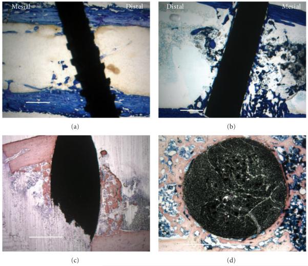
Figure 4.
Histological low-magnification imaging with all scale bars approximately 1.0 mm. (a) Lateral section of titanium-6-4 alloy implant as a representative image at the 0.8 mm implant distance (7.1 PBA from 10.5 PBA average) with toluidine blue stain. (b) Lateral section of bisphenyl-polymer/carbon-fiber composite implant was chosen as a representative image at the 0.8 mm implant distance (42.3 PBA from 41.6 PBA average) with toluidine blue stain. (c) Lateral intramedullary section of a bisphenyl-polymer/carbon-fiber composite implant from the fractured sample in Figure 2(c) that appears as dense cortical bone before alcohol and xylene solvent dehydration and clearing, respectively, instead provides contrast with a more trabeculated appearance after some osteoid removal using a modified H&E stain. So, additional osteoid not seen by histology is a probable in vivo structure at some level associated with the bisphenyl-polymer/carbon fiber implants. (d) Horizontal section of a bisphenyl-polymer/carbon-fiber implant from an extra tibial study not included in the statistical analysis provides an alternate view of the cut fiber ends to better appreciate the unidirectional composite with a Sanderson’s stain. The original implant diameters in all cases were approximately 1.5 mm.

