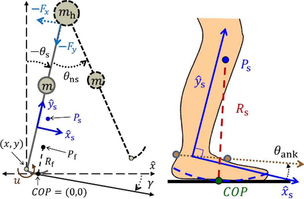
Fig. 1.
Left: biped model with the prosthesis shown in solid gray and the body shown in dashed black. The COP is defined at the origin, where the orientation of the global reference frame is defined with respect to horizontal (dashed) axis x̂. The origin of the shank-based coordinate frame (solid axes x̂s, ŷs) is drawn above the ankle for visual clarity but is actually modeled to coincide with the ankle joint (which is located at the heel for simplicity). Right: diagram of human ankle-foot effective shape with a radius of curvature Rs, which is constant for walking tasks. The COP moves along the shape (dashed curve) about the center of rotation Ps in the shank-based coordinate frame. Note that in this diagram the relative angle θank between the shank xs-axis and foot (dotted axis) is shown instead of the global leg angle θs.

