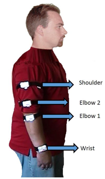
Figure 1.

Each white rectangle shows the placement of one Shimmer kinematic sensor on a participant’s arm during the session. Participants 1–3 were outfitted with all four sensors as shown, whereas Participants 4–6 were outfitted with only the Elbow 1 and Wrist sensors on each arm, rather than just the smoking arm. The reference coordinate frame is also shown.
