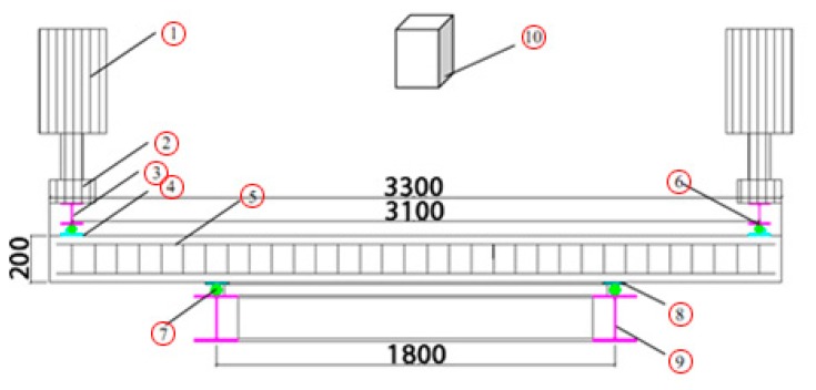
Figure 4.
Introduction of the test setup (Adapted from [15]). The Nos. in the picture are listed here: 1. Hydraulic jack; 2. Force sensors; 3. HEB 200 I-steel; 4. Steel plate of 5 mm; 5. Test specimen; 6. Steel tube (diameter: 5 mm); 7. Steel tube (diameter: 5 mm); 8. Steel plate of 5 mm; 9. I-steel frame (HEB 200); 10. Laser scanner.

