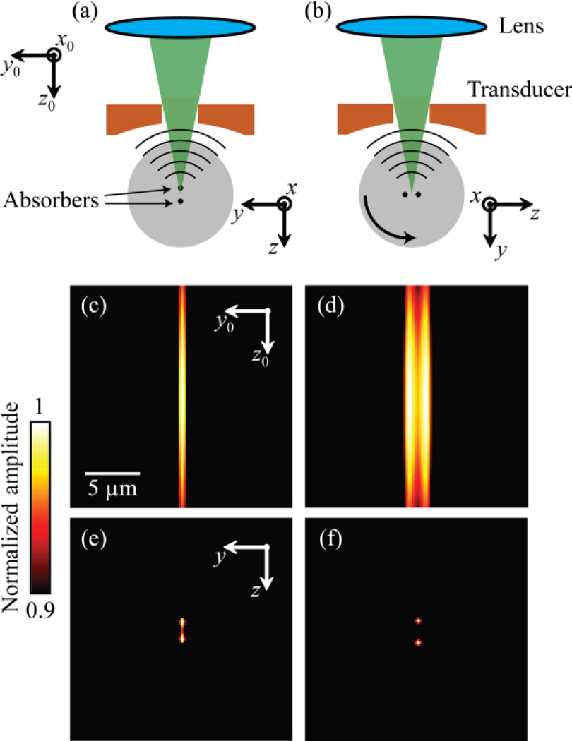
Fig. 1.
Principle and simulation of MV-OR-PAM. (a) Imaging two closely located (2 µm apart) point absorbers at angle 0° when the lab coordinate system is identical to the sample’s local coordinate system. (b) Rotate the sample by 90° and image it again. Notice the orientation of the absorbers and the local system are changed. (c, d) Acquired images from (a) and (b) under the global coordinate system. (e) Reconstructed image using MV-OR-PAM under the local coordinate system. (f) Ground truth image (blurred for display) of the two absorbers.

