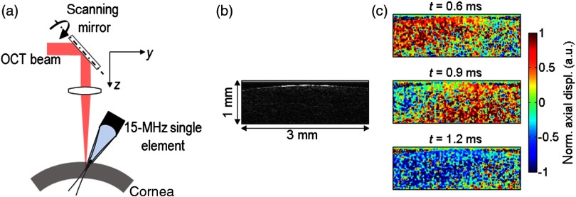
Fig. 8.
One-sided setup based on a 15-MHz single-element US transducer placed on the same side as the OCT imaging beam. (a) Schematic of the setup. (b) B-mode image of an ex vivo porcine cornea. (c) Snapshots of the propagation of the shear wave induced in an ex vivo porcine cornea at . The US transducer is placed on the left of the imaging range, and the shear wave propagated from left to right.

