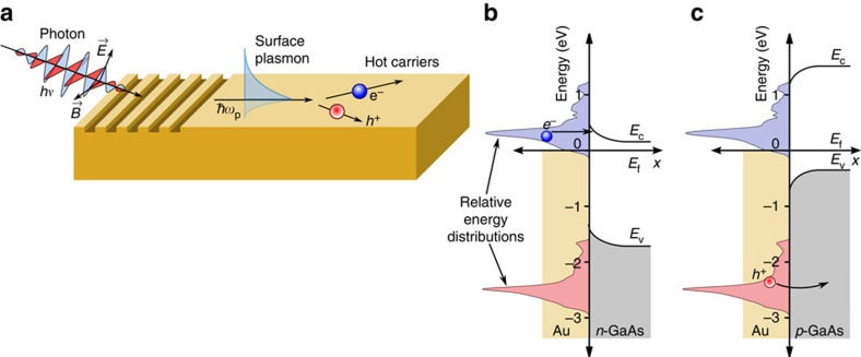
Figure 1. Schematic of plasmonic hot-carrier generation and injection.
(a) Schematic for optical excitation of surface plasmons followed by decay to hot carriers, (b) tunnelling of plasmonic hot electrons from gold through a Schottky barrier into n-type gallium arsenide using the predicted carrier distribution from Fig. 3d and typical experimental band offsets40 and (c) barrier-less injection of plasmonic hot holes from gold into p-type gallium arsenide. (Ef is the Fermi energy, Ec the conduction band minimum and Ev the valence band maximum energy.)

