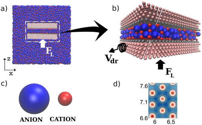
Figure 1. The sketch of the system.
(a) Side view of the typical configuration of the system under normal loading in the z-direction and sheared in y-direction. (b) Zoom of the confined region showing the IL confined between two walls. The upper wall is fixed and the bottom wall is loading with the force FL and pulling through the spring of stiffness, Kdr = 16 N/m, at constant velocity Vdr = 10 m/s. The dimensions of the walls are 7.56 nm and 7.95 nm in x and y directions, respectively, and the size of the atoms is σw = 0.3218 nm. (c) The diameters of the cations and anions are σc = 0.35 nm and σa = 0.70 nm, respectively. (d) Potential energy surface for cation sliding in x, y-directions along the surface, distances displayed in nm. Maxima and minima of the potential are shown by red and blue colors, respectively.

