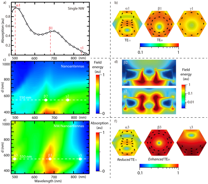
Figure 2.
(a) Calculated absorption spectra of a GaAs nanowire with a diameter of 150 nm in diameter lying on a glass substrate. For the points α1, β1 and γ1 the electric field intensity and the electric field lines are represented along the NW cross section in (b). (c) Calculated field energy map for an array of gold antennas on glass as a function of the wavelength and the inter-nanoantenna distance d. (d) Field energy distribution in the plane along the antennas axis corresponding to the points β2 and γ2. (e) Calculated absorption map for the nanowire/nanoantenna system on a glass substrate as a function of the nanoantenna distance d. The corresponding α3, β3 and γ3 electric field intensity and in-plane electric field lines are shown in (f). All the calculations were performed with light incident on the plane at perpendicular angle and transversely polarized with respect to the NW axis.

