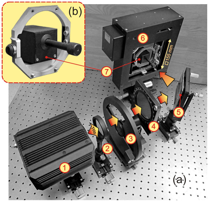
Figure 5. Quasi-optical experimental setup.
(a) Photograph of the experimental setup used for measuring the focusing performance of the developed HRAs: (1) – THz BWO, (2) – beam forming lens, (3) – chopper, (4) – wire grid polarizer, (5) – HRA (fixed to the optical holder), (6) – 2D raster scanner, (7) – pyroelectric detector. (b) Magnified photo of the pyro-detector mounted on the carrying metallic frame.

