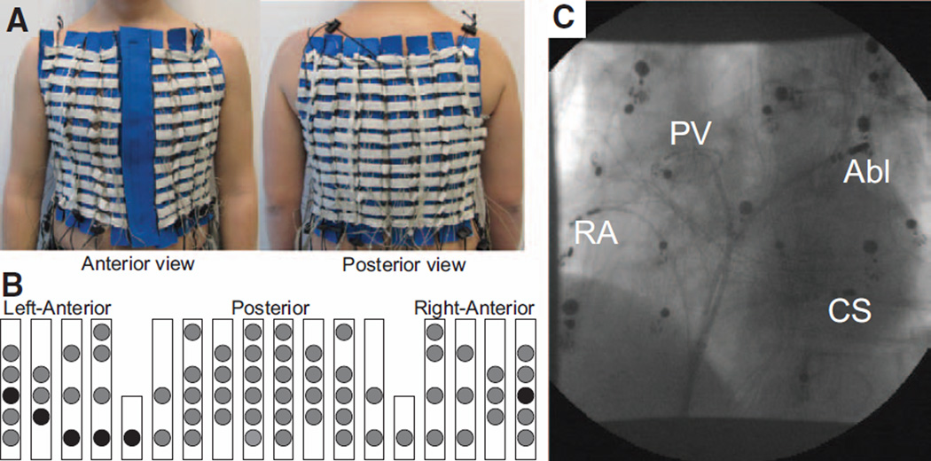
Figure 1.
The setup of the body surface recording electrodes. A, Anterior and posterior views of the custom-made vest with recording electrodes along vertical blue strips. B, Schematic location of surface electrodes. Circles represent the location of recording electrodes. Electrodes representing the standard ECG precordial leads are denoted as black circles. C, X-Ray image displaying the locations of the intracardiac recording catheters together with the surface leads. Abl indicates ablation catheter; CS, coronary sinus; PV, circular mapping at the right superior pulmonary vein; and RA, right atrium.

