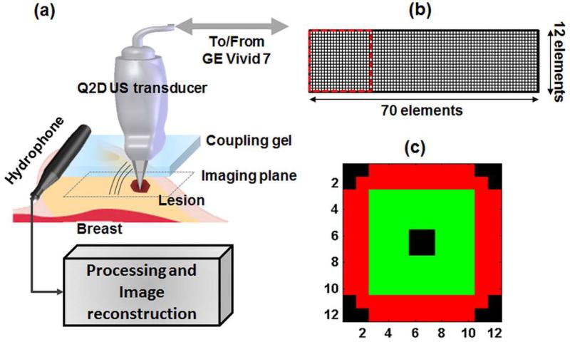
Figure 1.
(a). Block diagram of the VA imaging system incorporating a clinical US scanner equipped with a Q2D US transducer. The probe is moved by a motorized axis (not shown in figure) to mechanically scan the imaging plane (C-plane). (b) The element arrangement of the Q2D array US transducer utilizes 12 rows and 70 columns of piezoelectric elements. The active sub-aperture utilizes 144 elements within a square of 12 by 12 elements, marked with the dotted red square. (c) The active sub-aperture element configuration which includes a ring-shaped section, marked in red transmitting the ultrasonic waves at f1, and the central portion (green) that transmits at f2 (null-corner-center).

