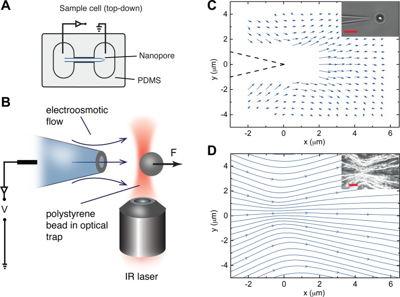
Figure 1.
Experimental setup for measuring a Landau–Squire flow. (A) A schematic of the sample cell made from PDMS which consists of a glass nanocapillary joining two reservoirs. The cell is sealed using a glass coverslip. (B) Using optical tweezers, a polystyrene bead is positioned close to the pore opening. An applied voltage generates electrokinetic flows which exert a force on the bead. (C) By moving the bead to different locations in the x–y plane, a force map can be generated; this can be converted to a velocity map using the Stokes formula. The flow field obeys the classical Landau–Squire solution, which is characterized by a parameter P representing the force required to set up the flow. Data from the flow map can be used to extract this number. (D) Particle image velocimetry measurements provide a more rigorous test of the Landau–Squire scaling as well as high-resolution velocity maps. Scale bars in the insets are 5 μm.

