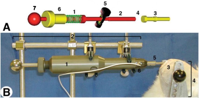
Figure 1.

(A) Impactor schematics. The compression of the spring in the load mechanism (A1) is controlled by the threaded screw (A6; 1 mm compression/360° of turn) mated with the housing of the impactor (not shown). Thus, the force applied to the missile on spring release is linearly related to the turns of the screw. Compression is accomplished by pulling the tensor knob (A7) until the release mechanism (A5) engages a notch in the piston. Activating the release mechanism (A5) releases the piston (A2) that collides with the interchangeable impactor missile (A3), which ultimately strikes the cartilage. The internal load cell (A4) is places in-line between the piston (A2) and missile (A3), and fixed to the latter. There is sufficient travel between the piston and projectile so that the piston does not contact the missile at the time of crtilage impact. (B) Setup for ex vivo impact of 5-mm cartilage plugs. (B) Setup for in situ impact showing the completed impactor (B1) in a fixed armature (B2) with a hemispherical tip B5) in contact with the left stifle, medial femoral condyle (B3) of a New Zealand White rabbit (euthanized) placed in its own armature (B4) contiguous with that of the impactor, and signal lead (B6) of internal load cell.
