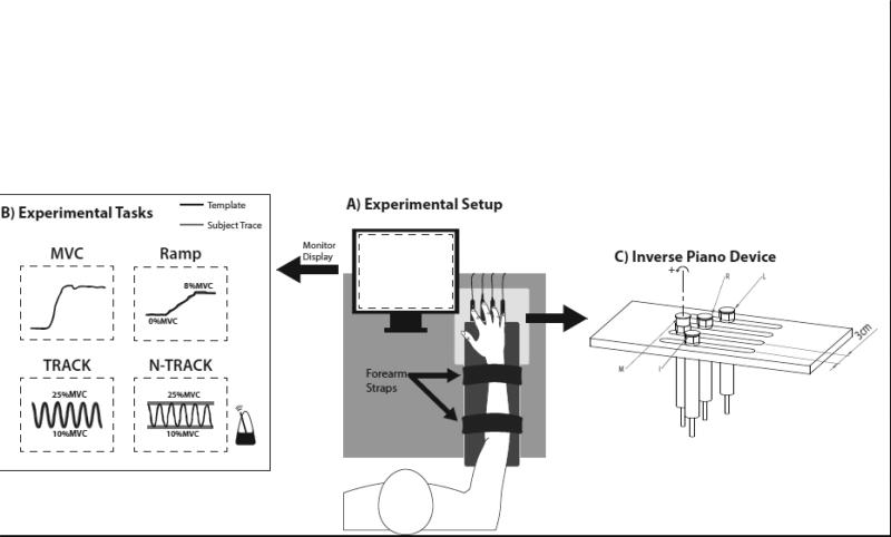
Figure 1.
A) A schematic of the experimental setup showing the subject's position and the sensor arrangement; B) Illustration of the feedback given to the subject on the monitor display. Signals for the maximum voluntary contraction (MVC), ramp force production, and cyclic force production with (TRACK) and without (N-TRACK) template are illustrated. A metronome paced the N-TRACK task; C) Schematic of force sensors mounted on linear motors. In the illustration, the ring force sensor is lifted. Moment arms with respect to mid-hand were 4.5 cm, 1.5 cm, -1.5 cm, and -4.5 cm for the index (I), middle (M), ring (R), and little (L) fingers, respectively. Counterclockwise rotation (+) around the axis represents pronation moment.

