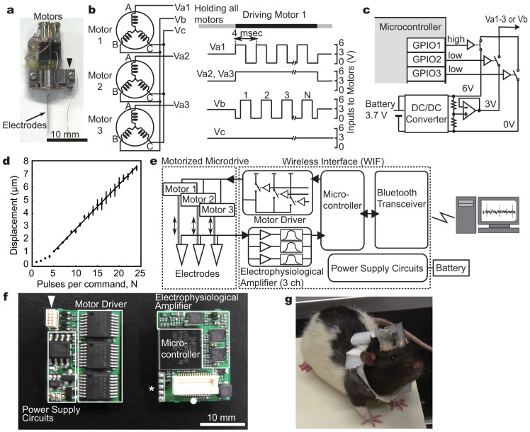
Figure 1. A wireless interface (WIF) for the motorized microdrive.
(a) A motorized microdrive with three recording electrodes. Electrodes and BLDCs are connected to the WIF through a small 10-pin connector (arrow head). (b) A wiring schematic between the BLDCs and the motor driver (left). An example set of the motor driver command for driving motor 1 (right). (c) A circuit diagram of the motor driver. Square voltage waves are synthesized by operation of three analog switches through the programmable input/output ports (GPIOs) in the microcontroller (MCU). (d) Precision control of the electrode movements by square voltage pulses. The average displacement of an electrode linearly increases as a function of the number of pulses when 5 or more square pulses are applied as the command signal. Error bars indicate ± s.e.m. (n = 10). (e) System overview. An electrophysiological amplifier, consisting of amplifier and filter circuits, is connected with the analog-to-digital converter (ADC) of the MCU, which converts analog recorded signals into digital data; a Bluetooth wireless transceiver is connected with the universal asynchronous receiver transmitter (UART) port of the MCU. (f) A circuit board of the WIF (both sides). An arrowhead, a closed circle, and an asterisk indicate a connector for the motorized microdrive, a connector for the Bluetooth transceiver, and the terminals for updating the firmware of the MCU, respectively. (g) A rat carrying a microdrive and WIF on the head, and a battery on the back.

