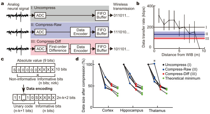
Figure 2. Data compression for stable wireless transmission.
(a) Schematics for signal processing of the recorded neuronal signals in the MCU. ADC, analog-to-digital converter; FIFO Buffer, first-in first-out ring buffer; Data Encoder, variable-length encoding process; First-order Difference, first-order difference operation. (b) The relationship between the data transfer rate and the distance. Thick horizontal black, blue, and red lines indicate the transfer rates required for real-time data transmission of neural signals with a fixed-length format (I), variable-length encoding process only (II), and first-order difference operation and variable-encoding process (III), respectively. Pale blue and red bands indicate s.d. in (II) and (III), respectively. (c) Data format before and after the variable-length encoding process. (d) Comparison of compression efficiency. Data size of the neuronal activity with a high firing rate (asterisk) became larger after the variable-length encoding process than the original. Note that the data could be compressed almost to the theoretical minimum size calculated by Shannon entropy.

