
Figure 3. Demonstration of wave transmission through anisotropic zero-index metamaterial loaded with defects.
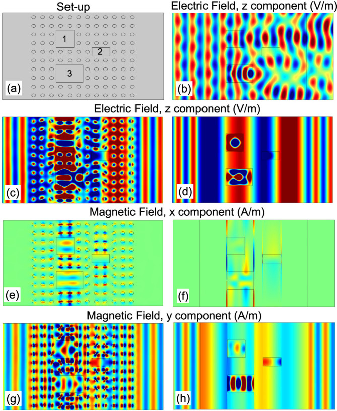
(a) Schematic of the sample, which is an air waveguide filled with a metamaterial slab (composed of 12 × 10 unit cells). Inside the metamaterial, there are three defects marked as “1”, “2”, and “3”, with respective sizes of 2a × 2b, 2a × b, and 3a × 2b, permeabilities μ = 1.5, 0.4, and 2.1, respectively, and permittivity 1. (b) Electric field pattern for a TE-polarized plane wave with frequency  incident from the left side of the waveguide without the metamaterial. (c) Electric field pattern, (e) the x-component of the magnetic field pattern, and (g) the y-component of the magnetic field pattern under the same excitation conditions as (b), but with the metamaterial slab in the waveguide. (d), (f), and (h) The same quantities as those described in (c), (e), and (g), respectively, but the metamaterial slab is replaced with an effective homogenous slab, which possesses effective medium parameters εeff = 0.1175, μeff,x = 0.0002, and μeff,y = 0.5637.