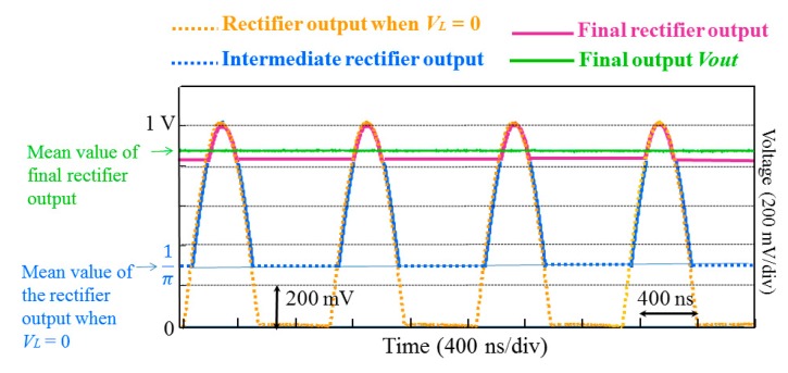
Figure 5.
Operation principle of the rectifier with a feedback into the limiter VL. The brown curve was measured on an oscilloscope when VL = 0. The green curve was also measured in steady state when the filter output is re-injected to VL (circuitry of Figure 4). The blue and magenta curves were drawn and superimposed on the measured curves for illustration only.

