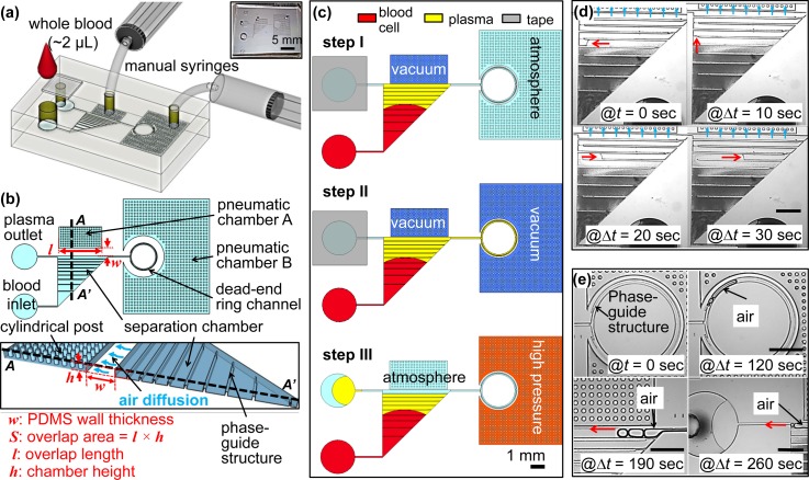
FIG. 1.
Schematics of the proposed device. (a) Overview of the experimental setup with the proposed device. The top layer is a PDMS cover with an inlet, a tape-sealed outlet and is bonded irreversibly with a bottom fluidic layer. (b) Top view and cross-section view. The separation chamber is divided into ten segments with equal volume by nine phaseguides at the bottom. Cylindrical posts are used to prevent the collapsing of the pneumatic chamber when it is vacuumed by the manual syringes. w and S stand for the PDMS wall thickness and the overlap area between the pneumatic chamber A and the separation chamber, respectively. The overlap area (S), where the flux of air diffuses, is calculated by the overlap length (l) multiplied by the chamber height (h). Drawings are not to scale. (c) Experimental steps. Step I: Apply vacuum at the pneumatic chamber A by pulling the syringe to 2 ml and add 2 μl of whole blood at the inlet (see Movie S1). Step II: after the separation chamber is filled with sample, the pneumatic chamber B is vacuumed in a similar way to the step I, which will withdraw the separated plasma into the dead-end ring channel. In this step, the separated plasma can be analysed with on-chip sensors, which is not a focus of this paper (see Movie S2). Step III: unseal the tape and apply high pressure at the pneumatic chamber B to push out the separated plasma to the plasma outlet by the help of the last phaseguide for further off-chip applications, which is an optional step (see Movie S3). (d) Image sequences taken from the filling process during the Step I. (e) Image sequences taken from the recovery process during the Step III. Red arrows in (d) and (e) indicate the flow directions, which shows the plasma/air interface flows along the phaseguides. Scale bars in (d) and (e) is 1 mm.

