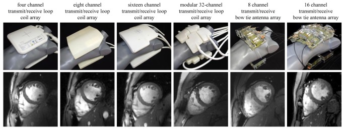
Figure 1. Synopsis of RF coil configurations used in this study.

Top: Photographs of the cardiac optimized 7.0 T transceiver RF coil arrays to illustrate the coil design and the coil geometry together with the coil positioning used in the UHF-CMR setting. The RF coils employed include a four channel [40], an eight channel [41], a 16 channel [9,42] and a 32 channel loop coil [43] configuration and an eight channel [44] and 16 channel bow tie antenna array configuration [45]. Bottom: Short axis views of the heart derived from 2D CINE FLASH acquisitions using the RF coil configurations in the top row and a spatial resolution of (1.4 x 1.4 x 4) mm3 and parallel imaging (R = 2, GRAPPA reconstruction).
