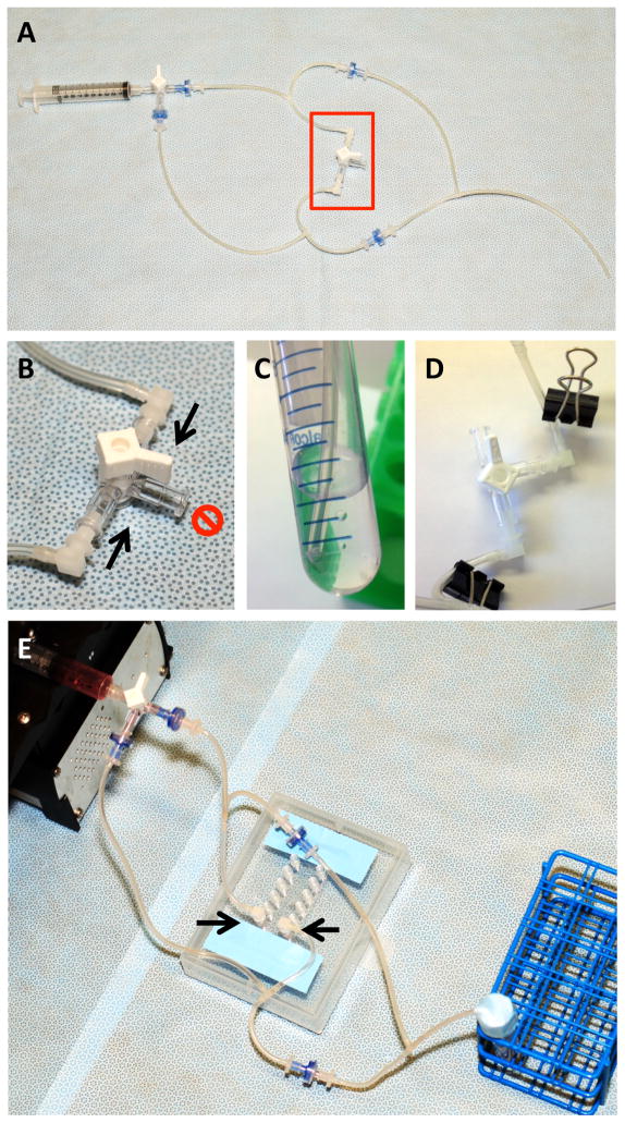
Figure 2.
Laminar shear stress tube assembly. A. Overview of the tube and check valve assembly. The second 3-way stopcock (red box) is temporary and serves as a “placeholder” for the future site of the slide. B. Two elbow connectors (arrows) are assembled to two female luer inlets of a 3-way stopcock before connecting to a slide. The third inlet (red “NO” symbol) is closed. C. Ensure the tubing in the media reservoir is close to but not in contact with the bottom of the 15 ml tube. D. To attach slide, first clamp the tubing on either side of the stopcock, then remove the stopcock. E. Connect the tube assembly to a slide by inserting the elbow connectors (arrows) into the two inlets of a channel (a 6-channel IBIDI VI0.4 slide is depicted).

