
Figure 1.
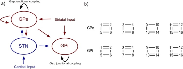
Placement of GJs added to the Rubin-Terman model [41]. (a) General setup of STN, GPe, GPi and inputs from striatum and cortex. Red indicates inhibitory connections, blue excitatory connections, black GJC. (b) GJ architectures in the GPe and GPi. Numbers represent the 16 cells in both nuclei, connected in groups of four via GJs and in the GPe also via inhibitory synapses (not shown). Light grey lines indicate the architecture for sparse GJC, dark grey lines the architecture for numerous GJC. [Color figure can be viewed in the online issue, which is available at wileyonlinelibrary.com.]