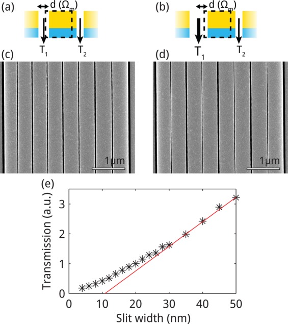
Figure 2.

Parallel mechanical transduction. Schematic of transduction through (a) constant-width and (b) alternating-width gaps. SEM micrographs of center of arrays of (c) constant-width gap (20 nm) and (d) alternating-width gap (20 and 50 nm) array structures. (e) Transmission through slit as a function of slit width d, extracted from FDTD simulations. The red line is a linear fit to the transmission through slits of width greater than 35 nm.
