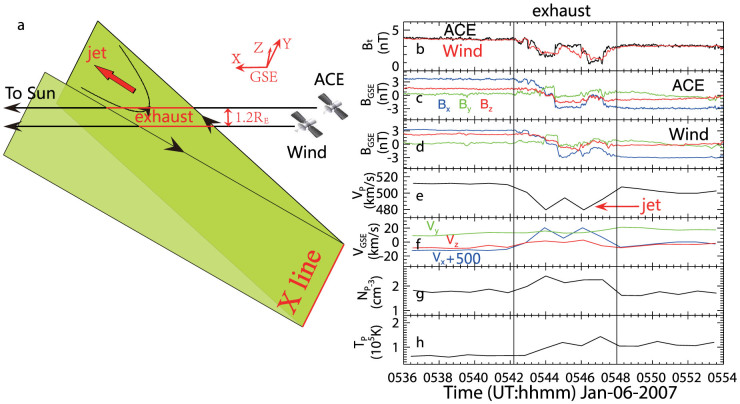
Figure 1. Schematics of spacecraft crossing a reconnection exhaust and selected measurements of magnetic field and plasma around the exhaust.
(a), sketch of the geometry of spacecraft encountering a solar wind reconnection exhaust. (b), magnetic magnitude. (c), the three components of magnetic field from ACE/MAG data. (d), the three components of magnetic field from Wind/MFI data. (e), the plasma bulk speed, showing a plasma jet. (f), the three components of plasma velocity by ACE. (g), proton density by ACE. (h), plasma temperature by ACE. The two vertical lines indicate the leading and trailing boundaries of the reconnection exhaust. The Wind/PM3DP data of 3-s resolution is not available during this interval. The main acceleration occurring in the +x direction indicates that a sunward directed exhaust was encountered. The X line is almost along the y-axis as illustrated below.

