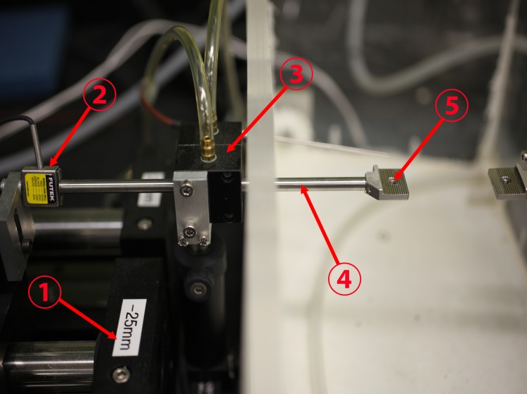
Figure 1.
Configuration of the load cell. A linear motor (1) was connected to a stain gauge (2) and transmitted its measured tensile force through a frictionless air bearing (3) and cylindrical shaft (4) to the moveable specimen clamp (5) to which one end of the specimen was affixed. The other specimen clamp at right was held immobile, anchoring the opposite end of the specimen. The environmental chamber at right surrounding the specimen was maintained at physiologic temperature and saturated humidity.

