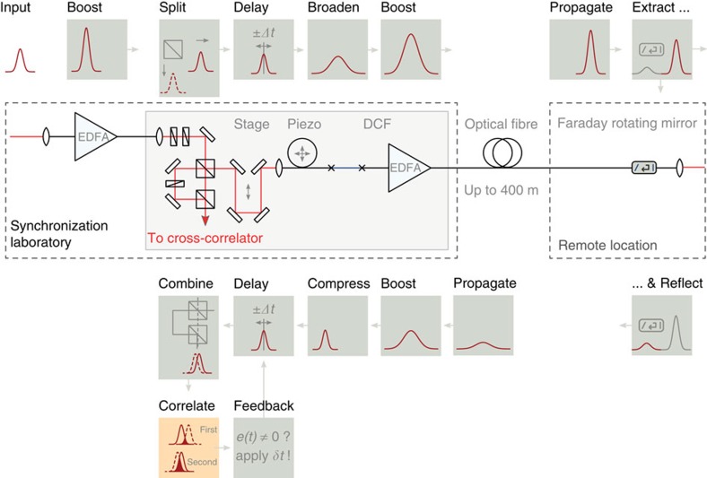
Figure 7. Fibre link stabilization.
In the fibre link, reference pulses are initially amplified in an erbium-doped fibre amplifier (EDFA). Then, the pulse is split with a polarizing beamsplitter. One component is immediately coupled into the optical cross-correlator, while the other component is propagated down the fibre optic cable that runs along the accelerator tunnel to the remote end station. At the end station, a semi-transparent mirror and a Faraday rotator, which rotates the polarization of the pulse by 90°, partially reflects the pulse back to the entrance of the link. The timing of the back-reflected pulse with respect to a reference laser pulse that has not been propagated through the fibre is then measured in the optical cross-correlator. Changes in the relative timing, corresponding to changes in the transit time or length of the optical fibre, can be used as feedback to stabilize the length of the fibre link using a fast piezo-based fibre-stretcher (‘Piezo’) and a motorized optical delay line (‘Stage’). To accommodate for pulse broadening in the link, a dispersion compensating fibre (DCF) is incorporated.

