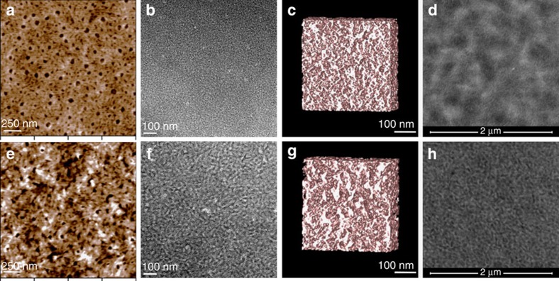
Figure 5. Solvent vapor annealing induced morphological changes.
(a) AFM image shows the topography of an as-cast BTR:PC71BM (1:1 weight ratio) blend film. (b) TEM bright-field image of the as-cast film taken at a defocusing range of 3 μm. (c) Computer model generated from the TEM tomogram of the as-cast film. (d) Low-energy HAADF STEM image of the as-cast film at focus using a beam energy of 15 keV. (e) AFM image of the BTR:PC71BM blend film after THF SVA for 15 s. (f) TEM bright-field image of the SVA-treated film at a defocusing range of 3 μm. (g) Computer model of the THF SVA film. (h) HAADF STEM image of the blend film after SVA treatment.

